Lesson 25 - Drawing mode and brush
In Lesson 14 - Canvas mode and auxiliary UI we introduced hand and selection modes, and in this lesson we'll introduce drawing modes: rectangles, ellipses, and arrows, as well as the more free-form brush modes.
Draw rect mode
First add the following canvas mode. The implementation of drawing ellipses is almost identical, so I won't repeat the introduction:
export enum Pen {
    HAND = 'hand',
    SELECT = 'select',
    DRAW_RECT = 'draw-rect',
    DRAW_Ellipse = 'draw-ellipse',
}
In Lesson 18 - Refactor with ECS we introduced the ECS architecture, where a DrawRect System is created, and once in that mode, the cursor style is set to crosshair:
import { System } from '@lastolivegames/becsy';

export class DrawRect extends System {
    execute() {
        if (pen !== Pen.DRAW_RECT) {
            return;
        }

        const input = canvas.write(Input);
        const cursor = canvas.write(Cursor);

        cursor.value = 'crosshair';
        //...
    }
}
Then as the mouse is dragged, the rectangle is continually redrawn in the target area, similar to the box selection effect in selection mode. When the mouse is lifted to complete the creation of the rectangle, it switches from draw rectangle mode to selection mode:
export class DrawRect extends System {
    execute() {
        //...
        // Draw rect brush when dragging
        this.handleBrushing(api, x, y);

        if (input.pointerUpTrigger) {
            // Create rect when pointerup event triggered
            const node: RectSerializedNode = {
                id: uuidv4(),
                type: 'rect', // Change to 'ellipse' in draw-ellipse mode
                x,
                y,
                width,
                height,
            };
            api.setAppState({ penbarSelected: Pen.SELECT }); // Switch canvas mode
            api.updateNode(node);
            api.record(); // Save to history
        }
    }
}
Next we look at what happens during the drag and drop process.
Redraw rect
Similar to box selection, in order to avoid dragging a small distance and starting to draw, we need to set a threshold, calculated in the Viewport coordinate system:
handleBrushing(api: API, viewportX: number, viewportY: number) {
    const camera = api.getCamera();
    const {
        pointerDownViewportX,
        pointerDownViewportY,
    } = camera.read(ComputedCameraControl);

    // Use a threshold to avoid showing the selection brush when the pointer is moved a little.
    const shouldShowSelectionBrush =
        distanceBetweenPoints(
            viewportX,
            viewportY,
            pointerDownViewportX,
            pointerDownViewportY,
        ) > 10;
}
The x/y coordinates of the auxiliary rectangle are where the pointerdown was triggered, and the coordinates of the pointermove event object need to be converted to the Canvas coordinate system to compute the width and height:
const { x: cx, y: cy } = api.viewport2Canvas({
    x: viewportX,
    y: viewportY,
});

let x = pointerDownCanvasX;
let y = pointerDownCanvasY;
let width = cx - x;
let height = cy - y;

api.updateNode(
    selection.brush,
    {
        visibility: 'visible',
        x,
        y,
        width,
        height,
    },
    false,
);
It is worth to consider the scenario of reverse dragging, where the calculated width/height may be negative, and the corresponding x/y will no longer be at the position of the pointerdown and will have to be recalculated. Figma does the same:
if (width < 0) {
    x += width;
    width = -width;
}
if (height < 0) {
    y += height;
    height = -height;
}
Size label
We want to show the dimensions of the rectangle in real time during the drawing process, like Figma does:
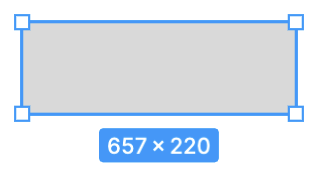
Similarly, annotations in this type of viewport space are well-suited for placement within SVG containers, as demonstrated by the laser pointer and eraser tools described below. Rectangular labels utilize CSS styles to set background color, padding, centering, and other properties, while text content employs the bounding box's width and height:
label.style.visibility = 'visible';
label.style.top = `${y + height}px`;
label.style.left = `${x + width / 2}px`;
label.innerText = `${Math.round(width)} × ${Math.round(height)}`;
If drawing a straight line, labels can rotate along the line's direction while ensuring text always faces forward. You can experience this in the arrow example in the next section:
label.style.top = `${y + height / 2}px`;
const rad = Math.atan2(height, width);
let deg = rad * (180 / Math.PI);
if (deg >= 90 && deg <= 180) {
    deg = deg - 180;
} else if (deg <= -90 && deg >= -180) {
    deg = deg + 180;
}
label.style.transform = `translate(-50%, -50%) rotate(${deg}deg)`;
Draw perfect square with shift
Hold down Shift when dragging to create perfect squares, circles and polygons. At this point, the minimum absolute value of the width and height is used as the side length of the square.
if (isSquare) {
    if (Math.abs(width) > Math.abs(height)) {
        width = Math.sign(width) * Math.abs(height);
    } else {
        height = Math.sign(height) * Math.abs(width);
    }
}
Draw arrow
Beyond basic shapes like rectangles, ellipses, and polylines, composite shapes such as arrows are also commonly used. We will not cover arrow binding relationships (where the arrow's direction changes when the shapes connected by its head and tail move) at this time; this topic will be addressed in a separate chapter. Here, we focus solely on how arrows are drawn.
Arrows are first declared in SVG using a <marker>, usually a <path>, and then associated with arrows via the marker-start and marker-end attributes of the target graphic:
<defs>
    <!-- arrowhead marker definition -->
    <marker
        id="arrow"
        viewBox="0 0 10 10"
        refX="5"
        refY="5"
        markerWidth="6"
        markerHeight="6"
        orient="auto-start-reverse"
    >
        <path d="M 0 0 L 10 5 L 0 10 z" />
    </marker>
</defs>
<!-- Coordinate axes with a arrowhead in both direction -->
<polyline
    points="10,10 10,90 90,90"
    fill="none"
    stroke="black"
    marker-start="url(#arrow)"
    marker-end="url(#arrow)"
/>
This way of separating the arrow endpoints from the body is very flexible. However, in a graphical editor scenario, it is sufficient to provide some preset common styles. For example, the arrow in Figma is realized by attaching it to the two endpoints of the Path (start/end point), with several preset styles such as line/triangle/diamond, see How to Curve an Arrow in Figma.
drawio also provides a lot of out-of-the-box arrow styles:
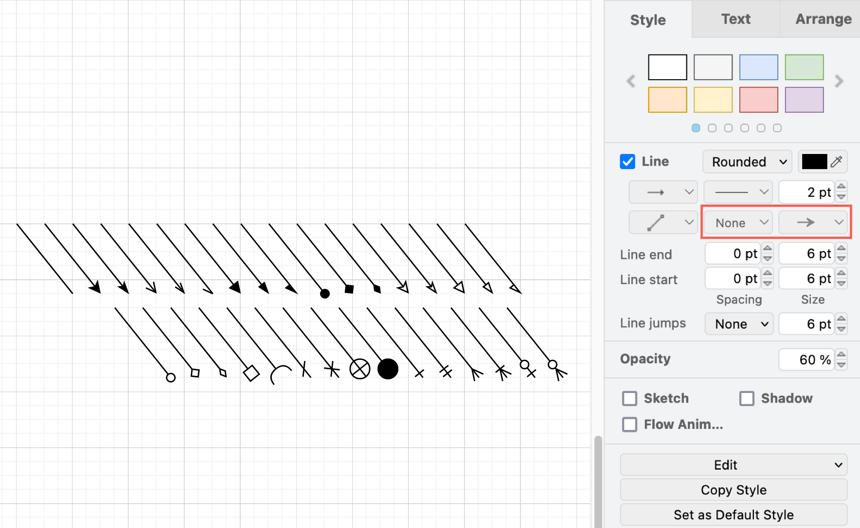
So in declarative usage, it's perfectly acceptable to sacrifice the feature of custom arrow styles and provide a set of built-in arrow style literals that generate the arrow endpoints along with the body when constructing the Polyline / Path. This idea can also be seen in plot - arrow rendered using SVG, which doesn't use <marker>, but a full <path> definition.
export interface MarkerAttributes {
    markerStart: Marker['start'];
    markerEnd: Marker['end'];
}
Next, let's look at the geometry construction process.
Start and end point
First you need to find the start and end points of the arrows.
However, the orientation needs to be calculated manually, which is not complicated, along the tangent line.
Export arrow to SVG
In SVG, you can adjust the orientation of <marker> using the orient attribute, but note that this attribute only has two literal values: ‘auto’ and ‘auto-start-reverse’.
if (isEnd) {
    $marker.setAttribute('orient', 'auto');
} else {
    $marker.setAttribute('orient', 'auto-start-reverse');
}
Then create a <path> based on the marker type, allowing it to inherit properties such as stroke from the target graphic. You can find the whole SVG in export arrow test case:
if (marker === 'line') {
    const points = lineArrow(0, 0, arrowRadius, Math.PI);
    const $path = createSVGElement('path');
    $path.setAttribute('fill', 'none');
    $path.setAttribute('stroke', stroke);
    $path.setAttribute('stroke-width', `${strokeWidth}`);
    $marker.appendChild($path);
}
In contrast, exported SVG files must also support re-importing into the canvas.
Draw polygon
Given a rectangular bounding box, programmatically generate a polygonal path:
function regularPolygonPathInRect(
    sides: number,
    width: number,
    height: number,
    rotation = -Math.PI / 2,
): string {
    if (sides < 3 || width <= 0 || height <= 0) {
        return '';
    }

    const cx = width / 2;
    const cy = height / 2;
    const rx = width / 2;
    const ry = height / 2;
    const step = (Math.PI * 2) / sides;
    const points: [number, number][] = [];

    for (let i = 0; i < sides; i++) {
        const angle = rotation + i * step;
        points.push([
            formatNumber(cx + Math.cos(angle) * rx),
            formatNumber(cy + Math.sin(angle) * ry),
        ]);
    }

    return points
        .map(([x, y], index) => `${index === 0 ? 'M' : 'L'} ${x} ${y}`)
        .join(' ')
        .concat(' Z');
}
Pencil tool
Let's start by looking at the simplest implementation, using a folded line display, called a Pencil in Figma.
In order to minimize the number of vertices generated by dragging and dropping, and especially the number of duplicated vertices or vertices in close proximity to each other, we will simplify the polyline using the method described in Lesson 12 - Simplify polyline, by choosing the simplify-js implementation. It is worth noting the definition of the tolerance parameter, which affects the degree of simplification:
Affects the amount of simplification (in the same metric as the point coordinates).
We want to set the tolerance differently depending on the current camera zoom level, otherwise the jitter caused by oversimplification at high zoom levels will be easily visible:
import simplify from 'simplify-js';

export class DrawPencil extends System {
    private handleBrushing() {
        // choose tolerance based on the camera zoom level
        const tolerance = 1 / zoom;
        selection.points = simplify(selection.pointsBeforeSimplify, tolerance);
    }
}
Perfect freehand
Since the line width is fixed, it lacks a sense of “flexibility.” To create a hand-drawn feel, lines can be made to vary with pressure. For this purpose, we can use perfect-freehand. It's worth noting that this feature is not yet integrated into Excalidraw; see: Perfect Freehand Drawing Issue. Because the line width is variable, the final drawn shape is no longer a Polyline but a Path:
import { getStroke } from 'perfect-freehand';

const outlinePoints = getStroke(points);
const d = getSvgPathFromStroke(outlinePoints); // 'M 0 0 L...'
By default, perfect-freehand simulates the speed of brushstrokes by calculating variable line widths based on the distance between adjacent points. To use real pressure, such as that from a pen or stylus, provide the pressure as the third number for each input point:
export class Input {
    @field.float32 declare pressure: number;
}
And set the simulatePressure option to false.
const outlinePoints = getStroke(inputPoints, {
    simulatePressure: false,
});
Brush mode
You can select this sub-tool when you enter Paint mode in Photoshop Web and draw strokes by dragging and dropping continuously:
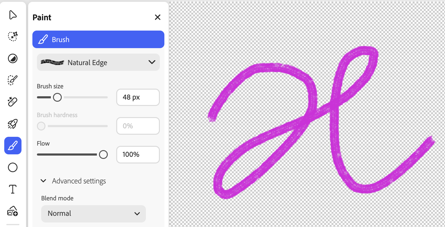
In Figma it is called Draw with illustration tools.
If we look closely at this type of stroke, we can see that it consists of a set of consecutive dots, which, if they have different radii, can give the effect of variable thickness. This can be realized by mapping the pressure of the brush to the radius:
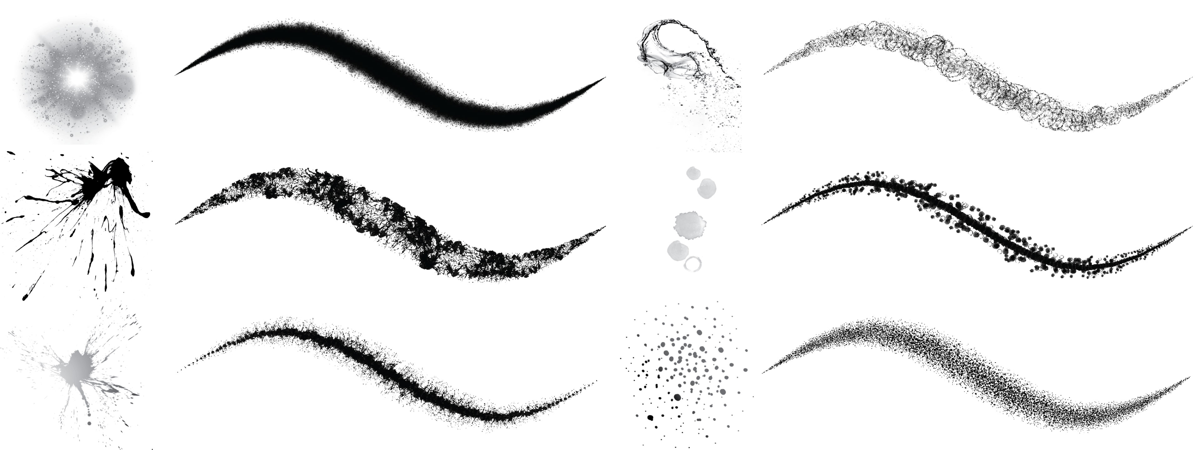
Here we refer to Brush Rendering Tutorial to realize this effect.
Basic implementation
The underlying data structure is as follows:
interface BrushPoint {
    x: number;
    y: number;
    radius: number;
}
The
renderPass.drawIndexed(6, points.length - 1); // indices: [0, 1, 2, 0, 2, 3]As we saw in Lesson 12 - Extrude segment, you can pass a_VertexNum into the Vertex Shader, or you can use gl_VertexID directly as in Brush Rendering Tutorial if you don't want to take into account WebGL 1 compatibility:
layout(location = ${Location.POINTA}) in vec3 a_PointA;
layout(location = ${Location.POINTB}) in vec3 a_PointB;
layout(location = ${Location.VERTEX_NUM}) in float a_VertexNum; // [0, 1, 2, 3]
By the way the other attributes, a_PointA and a_PointB store variable radii in addition to vertex position coordinates. Again we use vertexBufferOffsets to multiplex the same Buffer, and a_PointB reads from an offset of 4 * 3. This way we have the vertex numbers to stretch in the Vertex Shader:
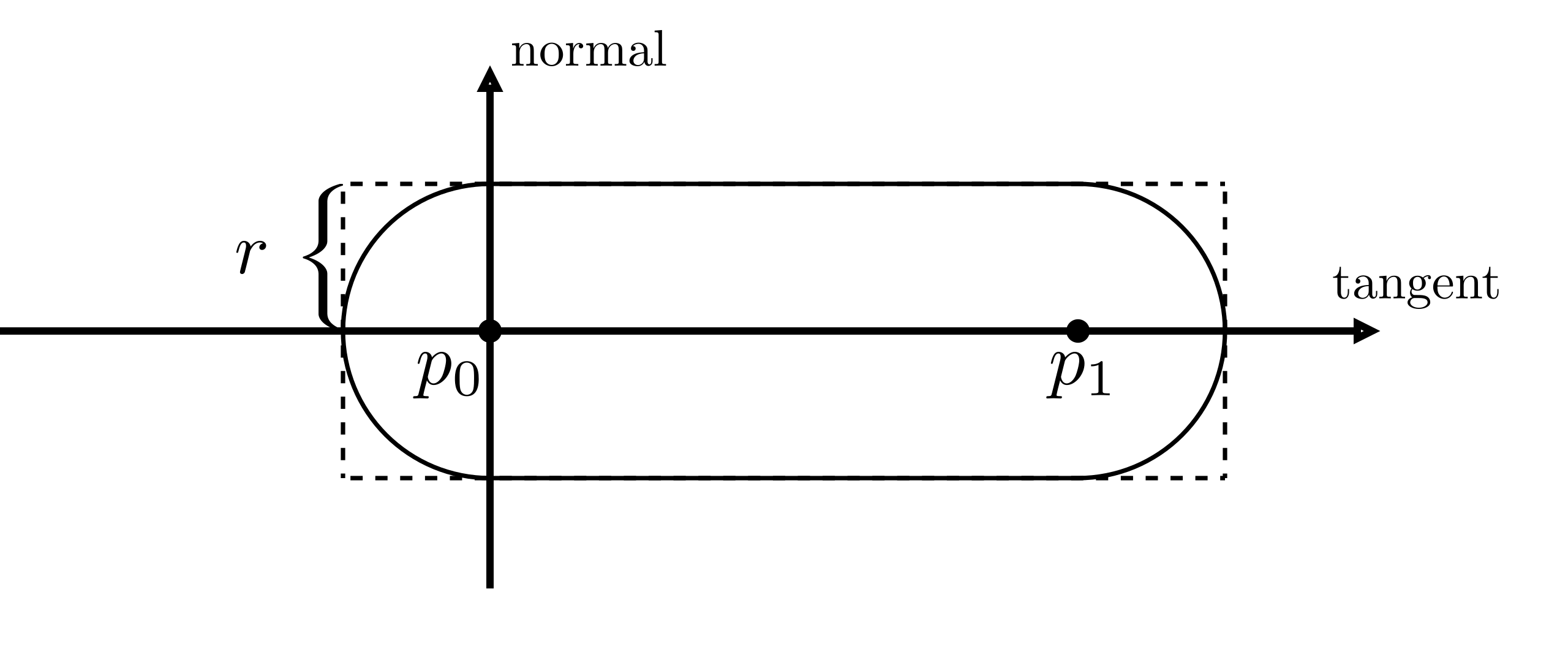
vec2 position;
vec2 offsetSign;
float r;
if (vertexNum < 0.5) {
position = p0;
r = r0;
offsetSign = vec2(-1.0, -1.0);
} else if (vertexNum < 1.5) {
position = p0;
r = r0;
offsetSign = vec2(-1.0, 1.0);
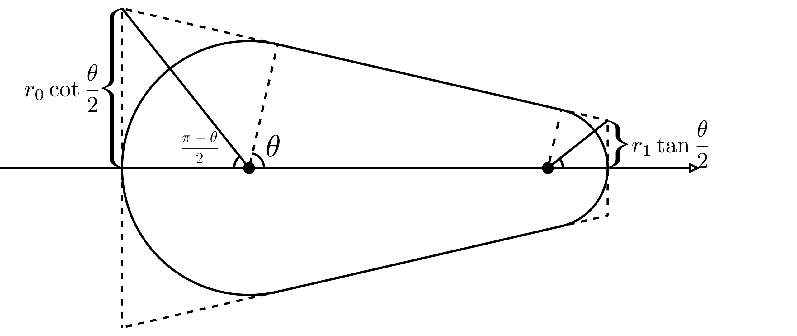
}In order to support variable widths, the stretched distance is not always equal to the radius of the current point, but needs to be calculated based on the slope of the line segment:
int MAX_i = 128; float currIndex = startIndex;
float A = 0.0;
for(int i = 0; i < MAX_i; i++){
    // Blend opacity
    A = A * (1.0-opacity) + opacity;
}
The effect is as follows:
Stamp
This doesn't quite work like a real brushstroke. We add brushStamp property for stamp image url, but it just control the opacity of the brush, stroke still effects the color.
api.updateNodes([
    {
        id: '1',
        type: 'brush',
        brushType: BrushType.STAMP,
        brushStamp: '/stamp.png',
        points: position.map(([x, y], i) => `${x},${y},${radius[i]}`).join(' '),
        stroke: 'grey',
    },
]);
Currently, all textures are applied in a fixed orientation. We can add random rotation angles to textures:
float angle = rotationFactor*radians(360.0*fract(sin(currIndex)*1.0));
pToCurrStamp *= rotate(angle);
We can also use noise factor when blend opacity:
float opacityNoise = noiseFactor*fbm(textureCoordinate*50.0);[WIP] Export SVG
Figma is able to export Brush to SVG.
Laser pointer
When implementing presentation features on the canvas, a laser pointer is an essential function. Excalidraw supports this capability, as detailed in: laser pointer. We can directly utilize its encapsulated @excalidraw/laser-pointer module, which generates a trajectory path based on a set of input point coordinates. This functionality also leverages perfect-freehand at its core.
This feature differs from previously drawn shapes on the canvas in the following ways:
- Laser pointer trajectory rendering occurs within the viewport coordinate system, independent of the current canvas zoom level. This allows implementation within a standalone HTML container. See: Lesson 29 - HTML container
- Traces automatically fade after a set duration
- Designed for multi-user collaboration scenarios. See: Lesson 20 - Awareness and Presence
Eraser
Excalidraw supports the freedraw eraser. After selecting the eraser tool, shapes traced by the mouse cursor will appear “faded,” indicating they are about to be erased. Lifting the mouse completes the erasure.
In the implementation, we use the Perfect freehand technique introduced in the previous section to draw the drag path, but only store the most recent 4 points. Simultaneously, we detect the shapes passed over in real time, setting their opacity (but remember to save the original opacity for restoration upon cancellation), and remove the selected shapes when the mouse is lifted:
export class DrawEraser extends System {
    execute() {
        if (input.pointerUpTrigger) {
            api.runAtNextTick(() => {
                api.updateNode(brush, { visibility: 'hidden' }, false);
                api.setAppState({
                    penbarSelected: Pen.SELECT,
                });
                api.deleteNodesById(
                    Array.from(selected).map((e) => api.getNodeByEntity(e)?.id),
                );
                api.record();
            });
        }
    }
}
Non-atomic
Erasing entire shapes is sufficient for most scenarios, but non-atomic erasing proves more practical in freehand drawing contexts—such as breaking a straight line midway. Excalidraw currently lacks this feature; see: non-atomic erasing for linear & freedraw shapes. FigJam shares this limitation. If the canvas is rendered using Canvas or SVG, achieving this pixel-level erasure effect is indeed impossible.
Since our canvas is implemented using WebGL/WebGPU, the most suitable technique is the stencil buffer. First, draw the eraser's path onto the stencil buffer, then use it as a mask to redraw the scene. Taking OpenGL as an example (WebGL is entirely analogous):
// 1. Disable color/depth writes, enable stencil, and draw the eraser shape:
//    This writes “1” into the stencil where the eraser stamp is drawn.
glColorMask(false,false,false,false);
glDepthMask(false);
glEnable(GL_STENCIL_TEST);
glStencilFunc(GL_ALWAYS, 1, 0xFF);
glStencilOp(GL_REPLACE, GL_REPLACE, GL_REPLACE);
// draw eraser brush geometry here (e.g. a textured quad or circle)

glColorMask(true,true,true,true);
glDepthMask(true);
// 2. Now render the shapes with stencil test=EQUAL, so only pixels where stencil==1 pass:
glStencilFunc(GL_EQUAL, 1, 0xFF);
glStencilOp(GL_KEEP, GL_KEEP, GL_KEEP);
// draw all scene objects (they will only appear where eraser just wrote 1)
We'll introduce this later in Lesson 34 - Frame and clip.