Lesson 12 - Draw polyline
Let's continue adding basic shapes: polylines. In this lesson, you will learn the following:
- Why not use
gl.LINESdirectly? - Building Mesh in CPU or Shader
- Analyzing Shader details, including:
- Stretching vertices and joints
- Anti-aliasing
- Drawing dashed lines
- How to calculate the bounding box of a polyline?
$icCanvas = call(() => {
    return document.createElement('ic-canvas-lesson12');
});call(() => {
const { Canvas, Polyline, Rect } = Lesson12;
const stats = new Stats();
stats.showPanel(0);
const $stats = stats.dom;
$stats.style.position = 'absolute';
$stats.style.left = '0px';
$stats.style.top = '0px';
$icCanvas.parentElement.style.position = 'relative';
$icCanvas.parentElement.appendChild($stats);
$icCanvas.addEventListener('ic-ready', (e) => {
const canvas = e.detail;
const polyline1 = new Polyline({
points: [
[100, 100],
[100, 200],
[200, 100],
],
stroke: 'red',
strokeWidth: 20,
fill: 'none',
});
canvas.appendChild(polyline1);
const polyline2 = new Polyline({
points: [
[220, 100],
[220, 200],
[320, 100],
],
stroke: 'red',
strokeWidth: 20,
strokeLinejoin: 'bevel',
fill: 'none',
});
canvas.appendChild(polyline2);
const polyline3 = new Polyline({
points: [
[340, 100],
[340, 200],
[440, 100],
],
stroke: 'red',
strokeWidth: 20,
strokeLinejoin: 'round',
strokeLinecap: 'round',
fill: 'none',
});
canvas.appendChild(polyline3);
const polyline4 = new Polyline({
points: [
[100, 300],
[200, 300],
[300, 210],
[400, 300],
[500, 300],
],
stroke: 'red',
strokeWidth: 20,
strokeLinejoin: 'round',
strokeLinecap: 'round',
strokeDasharray: [10, 5],
fill: 'none',
});
canvas.appendChild(polyline4);
const rect2 = new Rect({
x: 500,
y: 100,
fill: 'black',
fillOpacity: 0.5,
stroke: 'red',
strokeWidth: 10,
dropShadowBlurRadius: 10,
dropShadowColor: 'black',
dropShadowOffsetX: 10,
dropShadowOffsetY: 10,
strokeDasharray: [5, 5],
});
rect2.width = 100;
rect2.height = 100;
canvas.appendChild(rect2);
});
$icCanvas.addEventListener('ic-frame', (e) => {
stats.update();
});
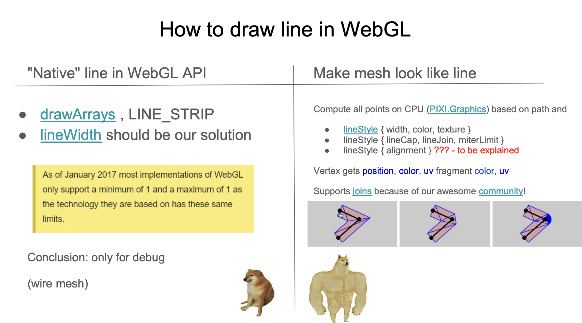
});Limitations of gl.LINES
The gl.LINES and gl.LINE_STRIP provided by WebGL are often not very practical in real scenarios:
- Do not support width. If we try to use lineWidth, common browsers such as Chrome will throw a warning:
WARNING
As of January 2017 most implementations of WebGL only support a minimum of 1 and a maximum of 1 as the technology they are based on has these same limits.
- Unable to define the connection shape between adjacent line segments lineJoin and the shape of the endpoints lineCap
- The default implementation has noticeable jaggies, requiring additional anti-aliasing
It should be noted that the solution in Lesson 5 - Line Grid is not suitable for drawing arbitrary line segments; it can't even define the two endpoints of a line segment arbitrarily. In addition, the biggest difference between line segments and polylines is the treatment at the joints, for which deck.gl provides LineLayer and PathLayer respectively.
Now let's clarify the features we want to implement for polylines:
- Support for arbitrary line widths
- Support for defining an arbitrary number of endpoints. Similar to the SVG points attribute.
- Support for connection shapes between adjacent line segments stroke-linejoin and endpoint shapes stroke-linecap
- Support for dashed lines. stroke-dashoffset and stroke-dasharray
- Good anti-aliasing effect
- Support for instanced drawing, see the previously introduced instanced drawing
Our designed API is as follows:
const line = new Polyline({
  points: [
    [0, 0],
    [100, 100]
  ],
  strokeWidth: 100,
  strokeLinejoin: 'round'
  strokeLinecap: 'round',
  strokeMiterlimit: 4,
  strokeDasharray: [4, 1],
  strokeDashoffset: 10
});
Let's first look at the first question: how to implement arbitrary values of strokeWidth.
Building mesh
The following image comes from the WebGL meetup shared by Pixi.js: How 2 draw lines in WebGL. This article will heavily reference screenshots from it, and I will label the page numbers in the PPT. Since native methods are not available, we can only return to the traditional drawing scheme of building Mesh.
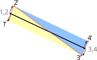
The common practice is to stretch and triangulate in the direction of the normal of the line segment. The following image comes from Drawing Antialiased Lines with OpenGL. The two endpoints of the line segment are stretched to both sides along the red dashed line normal, forming 4 vertices, triangulated into 2 triangles, so strokeWidth can be any value.
Building on CPU
The stretching of the line segment and the Mesh construction of strokeLinejoin and strokeLinecap can be done in the CPU or Shader. Implementations following the former approach include:

It can be seen that when strokeLinejoin and strokeLinecap take the value of round, in order to make the rounded corners look smooth, the Mesh construction requires the most vertices. In regl-gpu-lines, each segment requires up to 32 * 4 + 6 = 134 vertices:
// @see https://github.com/rreusser/regl-gpu-lines/blob/main/src/index.js#L81
cache.indexBuffer = regl.buffer(
    new Uint8Array([...Array(MAX_ROUND_JOIN_RESOLUTION * 4 + 6).keys()]), // MAX_ROUND_JOIN_RESOLUTION = 32
);
strokeLinecap and line segments need to be drawn in different Drawcall, still taking the instanced example of regl-gpu-lines as an example, it requires compiling two Programs and using 3 Drawcall to draw, among which:
- The two endpoints use the same Program, but the Uniform
orientationis different. The number of vertices iscap + join - All middle line segments are drawn using one Drawcall, the number of vertices is
join + join, and the number of instances is the number of line segments
const computeCount = isEndpoints
? // Draw a cap
(props) => [props.capRes2, props.joinRes2]
: // Draw two joins
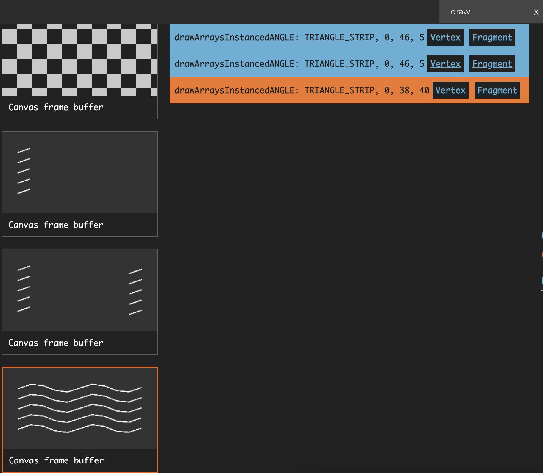
(props) => [props.joinRes2, props.joinRes2];If there are multiple polylines, the conditions for merging are the same values of strokeLinecap and strokeLinejoin and the number of line segments. The following figure shows the situation of drawing 5 polylines, among which each polyline's middle segment part contains 8 instance, so the total number of instance is 40:
Building in shader
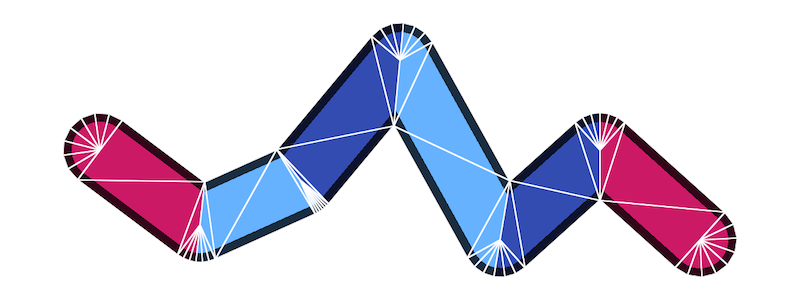
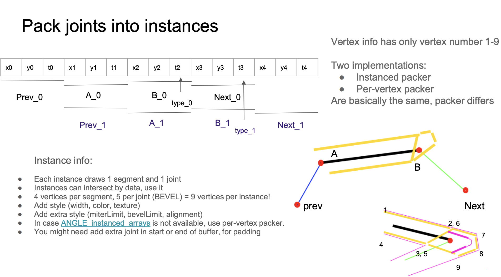
From the WebGL meetup shared by Pixi.js, building Mesh in Shader:
Compared with building on the CPU, its advantages include:
- Only one Drawcall is needed to draw
strokeLinecapstrokeLineJoinand the middle segment - The vertices are fixed at 9, where vertices 1234 form two triangles for drawing the line segment part, and vertices 56789 form three triangles for drawing the joint part
- When
strokeLinecapstrokeLinejointake the value ofround, it is smoother because a method similar to SDF drawing circles is used in the Fragment Shader - Good anti-aliasing effect
layout(location = ${Location.PREV}) in vec2 a_Prev;
layout(location = ${Location.POINTA}) in vec2 a_PointA;
layout(location = ${Location.POINTB}) in vec2 a_PointB;
layout(location = ${Location.NEXT}) in vec2 a_Next;
layout(location = ${Location.VERTEX_JOINT}) in float a_VertexJoint;
layout(location = ${Location.VERTEX_NUM}) in float a_VertexNum;
The Buffer layout is as follows, with each Stride size being 4 * 3. In the Buffer, the same continuous data such as x1 y1 t1 is read as A_0 in the first instance, and as Prev_1 in the second instance. This intersecting layout can save the maximum amount of Buffer size:
const vertexBufferDescriptors: InputLayoutBufferDescriptor[] = [
    {
        arrayStride: 4 * 3,
        stepMode: VertexStepMode.INSTANCE,
        attributes: [
            {
                format: Format.F32_RG,
                offset: 4 * 0,
                shaderLocation: Location.PREV,
            },
            {
                format: Format.F32_RG,
                offset: 4 * 3,
                shaderLocation: Location.POINTA,
            },
            {
                format: Format.F32_R,
                offset: 4 * 5,
                shaderLocation: Location.VERTEX_JOINT,
            },
            {
                format: Format.F32_RG,
                offset: 4 * 6,
                shaderLocation: Location.POINTB,
            },
            {
                format: Format.F32_RG,
                offset: 4 * 9,
                shaderLocation: Location.NEXT,
            },
        ],
    },
];
Unfortunately, if we switch to the WebGPU renderer, we will get the following error:
WARNING
Attribute offset (12) with format VertexFormat::Float32x2 (size: 8) doesn't fit in the vertex buffer stride (12).
The reason is that WebGPU has the following verification rule for VertexBufferLayout, and our arrayStride is 4 * 3. WebGPU instancing problem and spec: It is useful to allow GPUVertexBufferLayout.arrayStride to be less than offset + sizeof(attrib.format) also mention this.
attrib.offset + byteSize(attrib.format) ≤ descriptor.arrayStride.
4 3 + 4 2 ≤ 4 * 3 // Oops!
Therefore, we have to change the layout of the Buffer. First, in the Layout, we split the layout from one Buffer containing multiple Attributes to multiple Buffers, each containing only one Attribute:
const vertexBufferDescriptors: InputLayoutBufferDescriptor[] = [
    {
        arrayStride: 4 * 3,
        stepMode: VertexStepMode.INSTANCE,
        attributes: [
            {
                format: Format.F32_RG,
                offset: 4 * 0,
                shaderLocation: Location.PREV,
            },
        ],
    },
    {
        arrayStride: 4 * 3,
        stepMode: VertexStepMode.INSTANCE,
        attributes: [
            {
                format: Format.F32_RG,
                offset: 4 * 0,
                shaderLocation: Location.POINTA,
            },
        ],
    },
    // Omit VERTEX_JOINT
    // Omit POINTB
    // Omit NEXT
];
Although split into multiple BufferLayout declarations, the actual reference is to the same Buffer, only the corresponding Attribute is read via offset, see details: Offset in bytes into buffer where the vertex data begins。
const buffers = [
    {
        buffer: this.#segmentsBuffer, // PREV
    },
    {
        buffer: this.#segmentsBuffer, // POINTA
        offset: 4 * 3,
    },
    {
        buffer: this.#segmentsBuffer, // VERTEX_JOINT
        offset: 4 * 5,
    },
    {
        buffer: this.#segmentsBuffer, // POINTB
        offset: 4 * 6,
    },
    {
        buffer: this.#segmentsBuffer, // NEXT
        offset: 4 * 9,
    },
];
renderPass.setVertexInput(this.#inputLayout, buffers, {
    buffer: this.#indexBuffer,
});
Other features will also be implemented based on this scheme later.
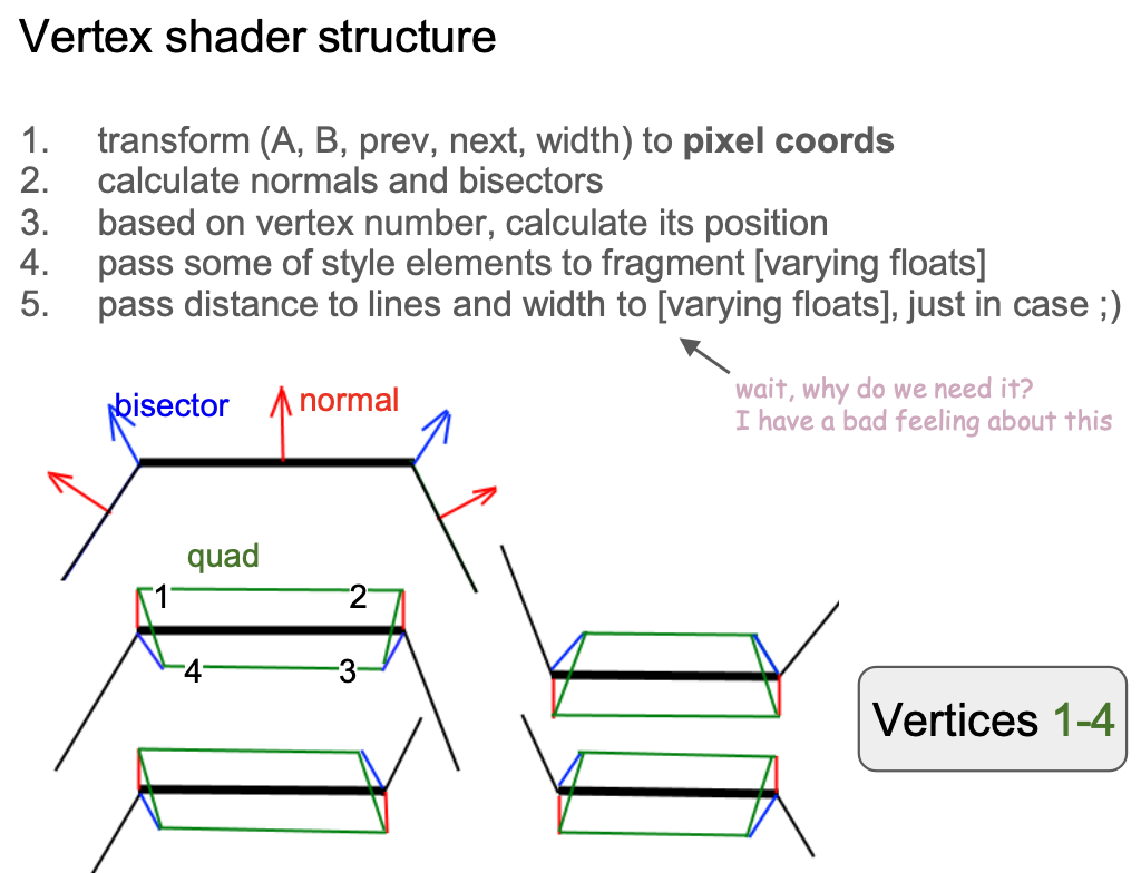
Shader implementation analysis
First, let's see how to stretch vertices at the main body and joints of the line segment.
Extrude segment
Let's focus on vertices 1 to 4, that is, the main part of the line segment. Considering the angle at which the line segment and its adjacent line segments present, there are the following four forms /-\ \-/ /-/ and \-\:
Before calculating the unit normal vector, convert the position of each vertex to the model coordinate system:
vec2 pointA = (model * vec3(a_PointA, 1.0)).xy;
vec2 pointB = (model * vec3(a_PointB, 1.0)).xy;

vec2 xBasis = pointB - pointA;
float len = length(xBasis);
vec2 forward = xBasis / len;
vec2 norm = vec2(forward.y, -forward.x);

xBasis2 = next - base;
float len2 = length(xBasis2);
vec2 norm2 = vec2(xBasis2.y, -xBasis2.x) / len2;
float D = norm.x * norm2.y - norm.y * norm2.x;
In the first form, for example, vertices 1 and 2 are stretched outward along the normal, and vertices 3 and 4 are stretched inward along the angle bisectors (doBisect()) of the joints:
if (vertexNum < 3.5) { // Vertex #1 ~ 4
    if (abs(D) < 0.01) {
        pos = dy * norm;
    } else {
        if (flag < 0.5 && inner < 0.5) { // Vertex #1, 2
            pos = dy * norm;
        } else { // Vertex #3, 4
            pos = doBisect(norm, len, norm2, len2, dy, inner);
        }
    }
}
Extrude linejoin
Next, we focus on vertices 5~9 at the joint, the stretching direction and distance varies according to the shape of the joint, the original author's implementation is very complex, in which bevel and round share the same stretching method, and the latter in the Fragment Shader and then through the SDF to complete the rounded corners of the drawing.
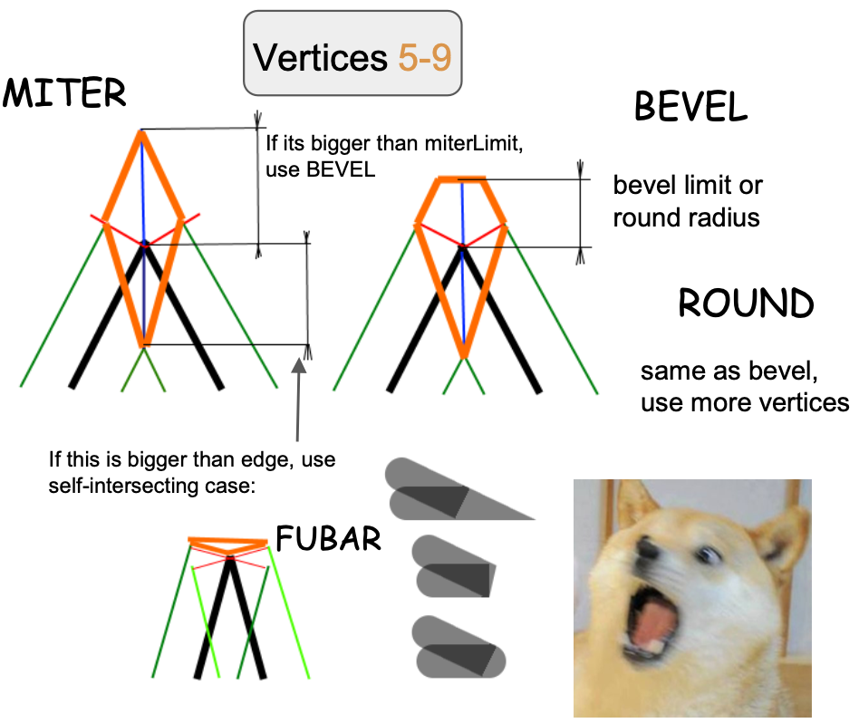
Let's start our analysis with the simplest miter, which by definition converts to bevel if strokeMiterlimit is exceeded.
if (length(pos) > abs(dy) * strokeMiterlimit) {
    type = BEVEL;
} else {
    if (vertexNum < 4.5) {
        dy = -dy;
        pos = doBisect(norm, len, norm2, len2, dy, 1.0);
    } else if (vertexNum < 5.5) {
        pos = dy * norm;
    } else if (vertexNum > 6.5) {
        pos = dy * norm2;
    }
    v_Type = 1.0;
    dy = -sign * dot(pos, norm);
    dy2 = -sign * dot(pos, norm2);
    hit = 1.0;
}
It is worth mentioning that in Cairo, whether to use round or bevel joints needs to be determined based on arc height. The following figure comes from: Cairo - Fix for round joins

Anti-aliasing
Finally, let's see how to anti-alias the edges of the line segment. We have introduced anti-aliasing in SDF before, and here we use a similar approach:
- Calculate the vertical unit vector from the vertex to the line segment in the Vertex Shader and pass it to the Fragment Shader through
varyingfor automatic interpolation - The interpolated vector is no longer a unit vector. Calculate its length, which is the perpendicular distance from the current pixel point to the line segment, within the range
[0, 1] - Use this value to calculate the final transparency of the pixel point, completing anti-aliasing.
smoothstepoccurs at the edge of the line segment, that is, within the interval[linewidth - feather, linewidth + feather]. The following figure comes from: Drawing Antialiased Lines with OpenGL, and the specific calculation logic will be introduced later.
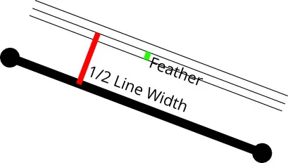
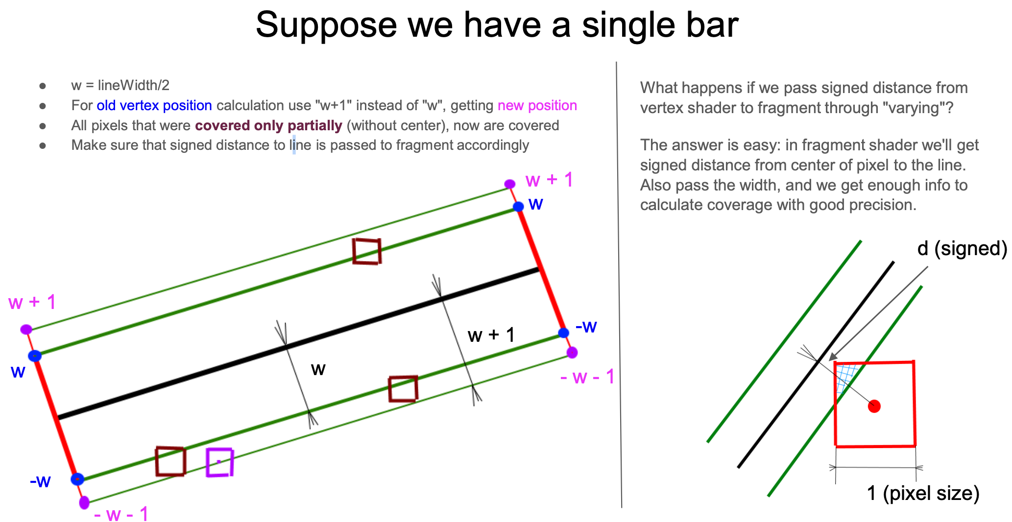
How much should this "feather" be? In the previous drawing rectangle outer shadow, we expanded the original size of the rectangle by 3 * dropShadowBlurRadius. The following figure still comes from How 2 draw lines in WebGL, expanding one pixel outward (from w -> w+1) is enough. At the other side, the distance of the two vertices (#3 and #4 vertices) is negative:
const float expand = 1.0;
lineWidth *= 0.5;

float dy = lineWidth + expand; // w + 1
if (vertexNum >= 1.5) { // Vertex #3 & #4
  dy = -dy; // -w - 1
}
From the bottom right figure, it can also be seen that when we zoom in to look at every pixel in the Fragment Shader, using this directed distance d, we can calculate the coverage of the line segment and the current pixel (the area of the triangle in the following figure), achieving an anti-aliasing effect.
So how to use this distance to calculate coverage? This needs to be divided into the main body of the line segment and the joint situation.
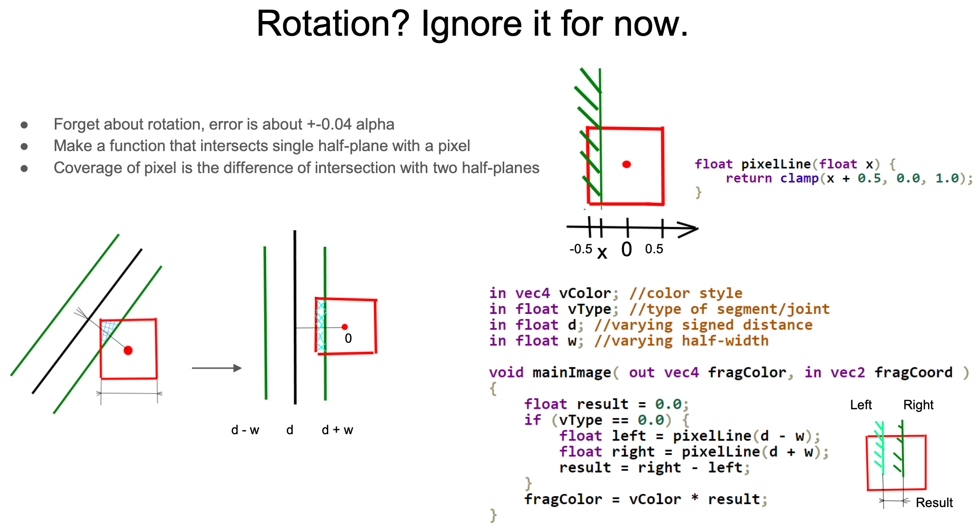
First, let's look at the situation of the main body of the line segment, which can be further simplified into the case of a vertical line segment. The original author also provided a calculation method considering rotation, which is not much different from the simplified estimation version. Use clamp to calculate the coverage on one side, and also consider the case of a very thin line width, subtract the left side from the right side to get the final coverage, as the transparency coefficient of the final color.
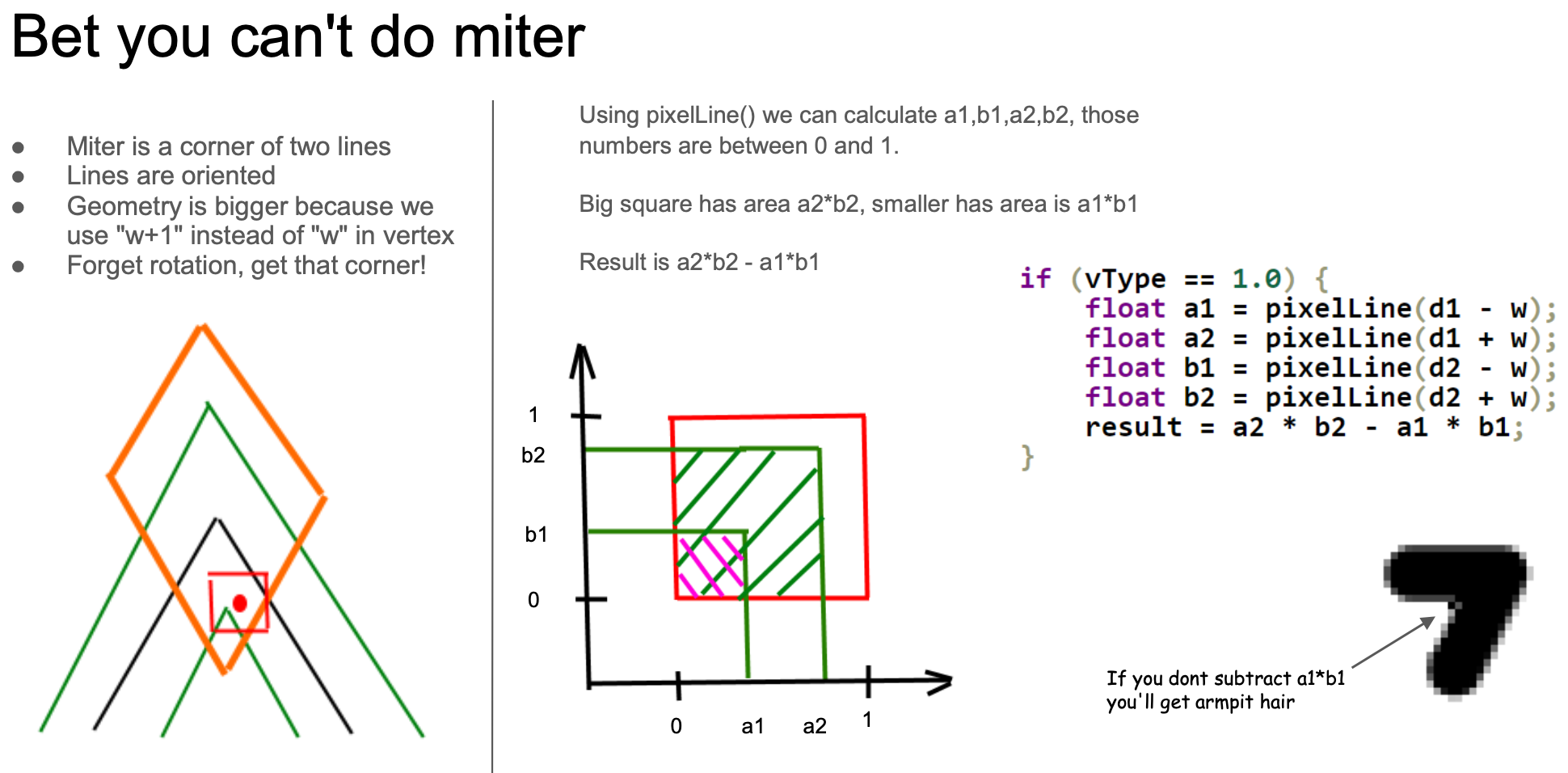
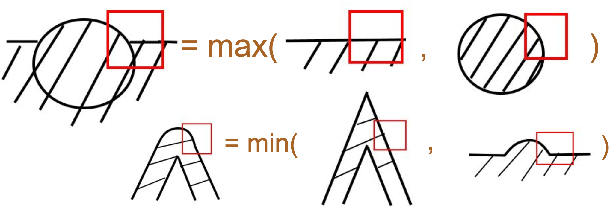
Of course, calculating the intersection area between the line segment part and the straight line is the simplest case. The treatment at the joints and endpoints will be very complex. Taking the Miter joint as an example, still ignore the rotation and only consider the case where the adjacent line segments are perpendicular (note the red box area on the right side of the following figure). Unlike the line segment above, which only has one directed distance d, here there are two directed distances d1 and d2 representing the front and back two line segments at the joint. Similarly, considering a very thin line within a pixel area, the coverage area is the area difference between the two squares (a2 * b2 - a1 * b1):
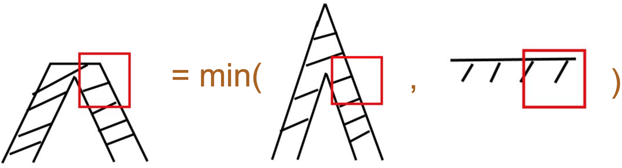
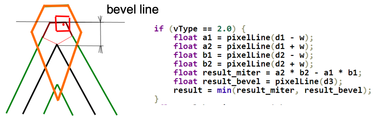
The calculation method for the Bevel joint is roughly the same as the Miter (the middle situation in the following figure). d3 represents the distance from the center of the pixel to the "bevel line", and it can be used to calculate the coverage on the right side of the following figure. You can take the minimum value of these two situations to get an approximate calculation result.
Finally, let's come to the case of rounded joints. It requires an additional distance d3 from the center of the circle to the pixel point (similar to SDF drawing circles) passed from the Vertex Shader.
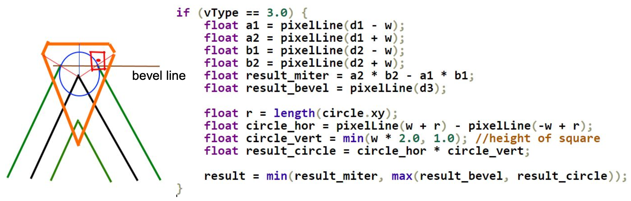
The original author also provided an exact version of pixelLine implementation, which will not be expanded due to space limitations.
Support for stroke-alignment
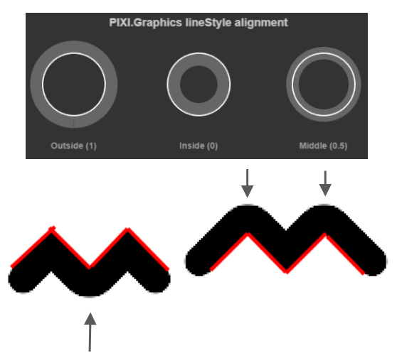
We previously implemented Enhanced SVG: Stroke alignment on Circle, Ellipse, and Rect drawn with SDF. Now let's add this attribute to polylines. The following figure comes from the lineStyle.alignment effect in Pixi.js, where the red line represents the geometric position of the polyline, and it floats up and down according to different values:
In the Shader, we reflect this attribute in the offset along the normal stretch. If the strokeAlignment takes the value of center, the offset is 0:
float shift = strokeWidth * strokeAlignment;
pointA += norm * shift;
pointB += norm * shift;
From left to right are the effects of outer, center, and inner:
$icCanvas2 = call(() => {
    return document.createElement('ic-canvas-lesson12');
});call(() => {
const { Canvas, Polyline } = Lesson12;
const stats = new Stats();
stats.showPanel(0);
const $stats = stats.dom;
$stats.style.position = 'absolute';
$stats.style.left = '0px';
$stats.style.top = '0px';
$icCanvas2.parentElement.style.position = 'relative';
$icCanvas2.parentElement.appendChild($stats);
$icCanvas2.addEventListener('ic-ready', (e) => {
const canvas = e.detail;
const polyline1 = new Polyline({
points: [
[100, 100],
[100, 200],
[200, 200],
[200, 100],
],
stroke: 'black',
strokeWidth: 20,
strokeAlignment: 'outer',
fill: 'none',
cursor: 'pointer',
});
canvas.appendChild(polyline1);
const polyline4 = new Polyline({
points: [
[100, 100],
[100, 200],
[200, 200],
[200, 100],
],
stroke: 'red',
strokeWidth: 2,
// strokeAlignment: 'outer',
fill: 'none',
});
canvas.appendChild(polyline4);
const polyline2 = new Polyline({
points: [
[220, 100],
[220, 200],
[320, 200],
[320, 100],
],
stroke: 'black',
strokeWidth: 20,
cursor: 'pointer',
fill: 'none',
});
canvas.appendChild(polyline2);
const polyline5 = new Polyline({
points: [
[220, 100],
[220, 200],
[320, 200],
[320, 100],
],
stroke: 'red',
strokeWidth: 2,
fill: 'none',
});
canvas.appendChild(polyline5);
const polyline3 = new Polyline({
points: [
[360, 100],
[360, 200],
[460, 200],
[460, 100],
],
stroke: 'black',
strokeWidth: 20,
strokeAlignment: 'inner',
fill: 'none',
cursor: 'pointer',
});
canvas.appendChild(polyline3);
const polyline6 = new Polyline({
points: [
[360, 100],
[360, 200],
[460, 200],
[460, 100],
],
stroke: 'red',
strokeWidth: 2,
fill: 'none',
});
canvas.appendChild(polyline6);
polyline1.addEventListener('pointerenter', () => {
polyline1.stroke = 'green';
});
polyline1.addEventListener('pointerleave', () => {
polyline1.stroke = 'black';
});
polyline2.addEventListener('pointerenter', () => {
polyline2.stroke = 'green';
});
polyline2.addEventListener('pointerleave', () => {
polyline2.stroke = 'black';
});
polyline3.addEventListener('pointerenter', () => {
polyline3.stroke = 'green';
});
polyline3.addEventListener('pointerleave', () => {
polyline3.stroke = 'black';
});
});
$icCanvas2.addEventListener('ic-frame', (e) => {
stats.update();
});
});Finally, there are two points to note:
- Since
stroke-alignmentis not a standard SVG attribute, it is necessary to recalculatepointswhen exporting to SVG, which is consistent with the logic of stretching along the normal and angle bisector in the Shader, which will not be expanded due to space limitations - The picking determination method, that is,
containsPoint, also needs to be calculated based on the offset vertices ofpoints. You can try to change the color of the polyline by moving the mouse in and out of the above example
Dashed lines
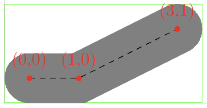
First, calculate the distance each vertex has traveled from the starting point. Taking the polyline of [[0, 0], [100, 0], [200, 0]] as an example, the a_Travel values of the three instances are [0, 100, 200]. Calculate the stretched vertex distance in the Vertex Shader:
layout(location = ${Location.TRAVEL}) in float a_Travel;
out float v_Travel;

v_Travel = a_Travel + dot(pos - pointA, vec2(-norm.y, norm.x));
In the Fragment Shader, pass in the values of stroke-dasharray and stroke-dashoffset. Different from the SVG standard, we only support stroke-dasharray of length 2 for the time being, that is, dashed lines like [10, 5, 2] are not supported.
in float v_Travel;

/**
虚线模式重复单元:
┌─────────────────┬─────────┬─────────────────┐
│   Gap/2         │  Dash   │   Gap/2         │
│  (Transparent)  │ (Opaque)│  (Transparent)  │
└─────────────────┴─────────┴─────────────────┘
       ↑                          ↑
      -0.5                   Dash+0.5
   (antialias)            (antialias)
 */
float u_Dash = u_StrokeDash.x;
float u_Gap = u_StrokeDash.y;
float u_DashOffset = u_StrokeDash.z;
if (u_Dash + u_Gap > 1.0) {
    /**
    value of travel:
  < -0.5          : gap region (alpha = 0)
  -0.5 ~ 0        : dash start edge (smooth transition)
  0 ~ Dash        : dash segment (alpha = 1)
  Dash ~ Dash+0.5 : dash end edge (smooth transition)
  > Dash+0.5      : gap region (alpha = 0)
     */
  float travel = mod(v_Travel + u_Gap * v_ScalingFactor * 0.5 + u_DashOffset, u_Dash * v_ScalingFactor + u_Gap * v_ScalingFactor) - (u_Gap * v_ScalingFactor * 0.5);
  float left = max(travel - 0.5, -0.5);
  float right = min(travel + 0.5, u_Gap * v_ScalingFactor + 0.5);
  alpha *= antialias(max(0.0, right - left));
}
We can also change (increment) stroke-dashoffset in real-time to achieve an ant line effect. Such animation effects are usually implemented through the SVG attribute of the same name, see: How to animate along an SVG path at the same time the path animates?
$icCanvas3 = call(() => {
    return document.createElement('ic-canvas-lesson12');
});call(() => {
const { Canvas, Polyline } = Lesson12;
const stats = new Stats();
stats.showPanel(0);
const $stats = stats.dom;
$stats.style.position = 'absolute';
$stats.style.left = '0px';
$stats.style.top = '0px';
$icCanvas3.parentElement.style.position = 'relative';
$icCanvas3.parentElement.appendChild($stats);
let polyline1;
$icCanvas3.addEventListener('ic-ready', (e) => {
const canvas = e.detail;
polyline1 = new Polyline({
points: [
[100, 100],
[100, 200],
[200, 200],
[200, 100],
],
stroke: 'black',
strokeWidth: 20,
strokeDasharray: [10, 10],
strokeDashoffset: 0,
fill: 'none',
cursor: 'pointer',
});
canvas.appendChild(polyline1);
const polyline2 = new Polyline({
points: [
[300, 100],
[300, 200],
[500, 200],
[500, 100],
],
stroke: 'black',
strokeWidth: 10,
strokeDasharray: [2, 10],
strokeDashoffset: 0,
strokeLinecap: 'round',
strokeLinejoin: 'round',
fill: 'none',
cursor: 'pointer',
});
canvas.appendChild(polyline2);
polyline1.addEventListener('pointerenter', () => {
polyline1.stroke = 'green';
});
polyline1.addEventListener('pointerleave', () => {
polyline1.stroke = 'black';
});
});
$icCanvas3.addEventListener('ic-frame', (e) => {
stats.update();
polyline1.strokeDashoffset += 0.1;
});
});Another implementation method uses fract(), see: Pure WebGL Dashed Line.
According to the SVG specification, the attributes stroke-dasharray and stroke-dashoffset can also be applied to other shapes such as Circle / Ellipse / Rect. Therefore, when these two attributes have reasonable values, the outline drawn with SDF originally needs to be changed to Polyline implementation. Taking Rect as an example, up to 3 drawcalls may be needed to draw the outer shadow, the main body of the rectangle, and the dashed outline:
SHAPE_DRAWCALL_CTORS.set(Rect, [ShadowRect, SDF, SmoothPolyline]);Taking Rect as an example, we need to artificially construct a polyline based on the x / y / width / height attributes, which includes 6 vertices. It is worth noting that the first 5 can actually complete the closure, but we add an extra [x + epsilon, y] to complete the final strokeLinejoin. Circle and Ellipse are similar, only adding more sampling points to ensure smoothness (here we use 64):
if (object instanceof Polyline) {
    points = object.points.reduce((prev, cur) => {
        prev.push(cur[0], cur[1]);
        return prev;
    }, [] as number[]);
} else if (object instanceof Rect) {
    const { x, y, width, height } = object;
    points = [
        x,
        y,
        x + width,
        y,
        x + width,
        y + height,
        x,
        y + height,
        x,
        y,
        x + epsilon,
        y,
    ];
}$icCanvas5 = call(() => {
return document.createElement('ic-canvas-lesson12');
});call(() => {
const { Canvas, Rect, Circle, Ellipse } = Lesson12;
const stats = new Stats();
stats.showPanel(0);
const $stats = stats.dom;
$stats.style.position = 'absolute';
$stats.style.left = '0px';
$stats.style.top = '0px';
$icCanvas5.parentElement.style.position = 'relative';
$icCanvas5.parentElement.appendChild($stats);
$icCanvas5.addEventListener('ic-ready', (e) => {
const canvas = e.detail;
const rect = new Rect({
x: 50,
y: 50,
fill: 'black',
fillOpacity: 0.5,
dropShadowBlurRadius: 10,
dropShadowColor: 'black',
dropShadowOffsetX: 10,
dropShadowOffsetY: 10,
stroke: 'red',
strokeWidth: 10,
});
rect.width = 100;
rect.height = 100;
canvas.appendChild(rect);
const rect2 = new Rect({
x: 200,
y: 50,
fill: 'black',
fillOpacity: 0.5,
stroke: 'red',
strokeWidth: 10,
dropShadowBlurRadius: 10,
dropShadowColor: 'black',
dropShadowOffsetX: 10,
dropShadowOffsetY: 10,
strokeDasharray: [5, 5],
});
rect2.width = 100;
rect2.height = 100;
canvas.appendChild(rect2);
const circle = new Circle({
cx: 400,
cy: 100,
r: 50,
fill: 'black',
stroke: 'red',
strokeWidth: 20,
strokeDasharray: [5, 5],
});
canvas.appendChild(circle);
const circle2 = new Circle({
cx: 550,
cy: 100,
r: 50,
fill: 'black',
stroke: 'red',
strokeWidth: 20,
strokeDasharray: [5, 20],
strokeAlignment: 'inner',
});
canvas.appendChild(circle2);
const ellipse = new Ellipse({
cx: 150,
cy: 250,
rx: 100,
ry: 50,
fill: 'black',
stroke: 'red',
strokeWidth: 20,
strokeDasharray: [5, 5],
});
canvas.appendChild(ellipse);
});
$icCanvas5.addEventListener('ic-frame', (e) => {
stats.update();
});
});Calculating the bounding box
Let's temporarily step out of rendering and do some geometric calculations. As introduced in previous lessons, bounding boxes need to be calculated in both picking and culling.
Ignoring drawing attributes such as line width, the calculation of the geometric bounding box is very simple. Just find the minimum and maximum coordinates of all vertices of the polyline:
const minX = Math.min(...points.map((point) => point[0]));
const maxX = Math.max(...points.map((point) => point[0]));
const minY = Math.min(...points.map((point) => point[1]));
const maxY = Math.max(...points.map((point) => point[1]));

return new AABB(minX, minY, maxX, maxY);
Once line width, endpoints, and joints are involved, calculating the bounding box of a polyline becomes more complex. If a precise result is not required, you can simply extend the aforementioned bounding box outward by half the line width. Calculate bounding box of line with thickness uses the cairo-stroke-extents method provided by Cairo. If the line width is 0, it will degrade into cairo-path-extents:
Computes a bounding box in user coordinates covering the area that would be affected, (the "inked" area)
Continuing to delve into the Cairo source code, it can be found that for stroke bounding boxes, it also provides two methods (omitting a large number of parameters here), the former uses an estimation method and is therefore faster, while the latter will consider the specific shapes of endpoints and joints for precise calculation:
cairo_private void
_cairo_path_fixed_approximate_stroke_extents ();

cairo_private cairo_status_t
_cairo_path_fixed_stroke_extents ();
Quick Estimation
This estimation refers to expanding a certain distance outward along the horizontal and vertical directions on the basis of the geometric bounding box: style_expansion * strokeWidth.
/*
 * For a stroke in the given style, compute the maximum distance
 * from the path that vertices could be generated.  In the case
 * of rotation in the ctm, the distance will not be exact.
 */
void
_cairo_stroke_style_max_distance_from_path (const cairo_stroke_style_t *style,
         const cairo_path_fixed_t *path,
                                            const cairo_matrix_t *ctm,
                                            double *dx, double *dy)
{
    double style_expansion = 0.5;

    if (style->line_cap == CAIRO_LINE_CAP_SQUARE)
 style_expansion = M_SQRT1_2;

    if (style->line_join == CAIRO_LINE_JOIN_MITER &&
 ! path->stroke_is_rectilinear &&
 style_expansion < M_SQRT2 * style->miter_limit)
    {
 style_expansion = M_SQRT2 * style->miter_limit;
    }

    style_expansion *= style->line_width;
}
Considering the case of stroke-linecap="square", the following figure shows that in the most ideal situation, style_expansion equals 0.5, that is, extending 0.5 * strokeWidth from the red body, and the black area is the bounding box of the <polyline>.
But if the polyline is slightly tilted at 45 degrees, the distance extended outward at this time is sqrt(2) / 2 * strokeWidth:
Similarly, the case of stroke-linejoin="miter" also needs to be considered. It can be seen that this estimation method will not precisely consider every vertex and joint, but only make the most optimistic estimate to ensure that the bounding box can accommodate the polyline.
Below we draw the bounding box of the polyline in real time, showing the different values of strokeLinecap from left to right:
$icCanvas6 = call(() => {
    return document.createElement('ic-canvas-lesson12');
});call(() => {
const { Canvas, Polyline, Rect } = Lesson12;
const stats = new Stats();
stats.showPanel(0);
const $stats = stats.dom;
$stats.style.position = 'absolute';
$stats.style.left = '0px';
$stats.style.top = '0px';
$icCanvas6.parentElement.style.position = 'relative';
$icCanvas6.parentElement.appendChild($stats);
function drawBounds(canvas, polyline) {
const { minX, minY, maxX, maxY } = polyline.getBounds();
const bounds = new Rect({
x: minX,
y: minY,
stroke: 'red',
fill: 'none',
});
bounds.width = maxX - minX;
bounds.height = maxY - minY;
canvas.appendChild(bounds);
}
$icCanvas6.addEventListener('ic-ready', (e) => {
const canvas = e.detail;
const polyline1 = new Polyline({
points: [
[100, 100],
[200, 200],
],
stroke: 'black',
strokeWidth: 20,
fill: 'none',
cursor: 'pointer',
});
canvas.appendChild(polyline1);
drawBounds(canvas, polyline1);
const polyline2 = new Polyline({
points: [
[300, 100],
[400, 200],
],
stroke: 'black',
strokeWidth: 20,
strokeLinecap: 'round',
fill: 'none',
cursor: 'pointer',
});
canvas.appendChild(polyline2);
drawBounds(canvas, polyline2);
const polyline3 = new Polyline({
points: [
[500, 100],
[600, 200],
],
stroke: 'black',
strokeWidth: 20,
strokeLinecap: 'square',
fill: 'none',
cursor: 'pointer',
});
canvas.appendChild(polyline3);
drawBounds(canvas, polyline3);
});
$icCanvas6.addEventListener('ic-frame', (e) => {
stats.update();
});
});Precise calculation
If you really want to calculate precisely? Cairo's idea is to first convert it into a Polygon, and then calculate its bounding box:
cairo_status_t
_cairo_path_fixed_stroke_extents (const cairo_path_fixed_t *path,
      const cairo_stroke_style_t *stroke_style,
      const cairo_matrix_t  *ctm,
      const cairo_matrix_t  *ctm_inverse,
      double    tolerance,
      cairo_rectangle_int_t  *extents)
{
    cairo_polygon_t polygon;
    cairo_status_t status;
    cairo_stroke_style_t style;

    _cairo_polygon_init (&polygon, NULL, 0);
    status = _cairo_path_fixed_stroke_to_polygon (path,
        stroke_style,
        ctm, ctm_inverse,
        tolerance,
        &polygon);
    _cairo_box_round_to_rectangle (&polygon.extents, extents);
    _cairo_polygon_fini (&polygon);

    return status;
}
Performance testing
Let's test the performance, showing several polylines each containing 20,000 points:
$icCanvas4 = call(() => {
    return document.createElement('ic-canvas-lesson12');
});call(() => {
const { Canvas, Polyline } = Lesson12;
const stats = new Stats();
stats.showPanel(0);
const $stats = stats.dom;
$stats.style.position = 'absolute';
$stats.style.left = '0px';
$stats.style.top = '0px';
$icCanvas4.parentElement.style.position = 'relative';
$icCanvas4.parentElement.appendChild($stats);
let polyline1;
$icCanvas4.addEventListener('ic-ready', (e) => {
const canvas = e.detail;
const data = new Array(20000)
.fill(undefined)
.map((_, i) => [i, Math.random() * 50]);
polyline1 = new Polyline({
points: data,
stroke: 'black',
strokeWidth: 2,
fill: 'none',
cursor: 'pointer',
});
canvas.appendChild(polyline1);
const data2 = new Array(20000)
.fill(undefined)
.map((_, i) => [i, Math.random() * 50 + 100]);
polyline2 = new Polyline({
points: data2,
stroke: 'black',
strokeWidth: 2,
strokeLinejoin: 'round',
fill: 'none',
cursor: 'pointer',
});
canvas.appendChild(polyline2);
const data3 = new Array(20000)
.fill(undefined)
.map((_, i) => [i, Math.random() * 50 + 200]);
polyline3 = new Polyline({
points: data3,
stroke: 'black',
strokeWidth: 2,
strokeDasharray: [4, 4],
fill: 'none',
cursor: 'pointer',
});
canvas.appendChild(polyline3);
});
$icCanvas4.addEventListener('ic-frame', (e) => {
stats.update();
});
});It seems not bad, but after careful consideration, there are still the following issues, which can be considered as future improvement directions:
- Due to the fact that each Instance uses 15 vertices, and the Buffer has a size limit, the actual number of vertices contained in a single polyline is limited
- Currently, one polyline corresponds to one Drawcall. What if there are a large number of similar repeated polylines? regl-gpu-lines provides two ideas:
- One Drawcall can also draw multiple polylines, using
[NaN, NaN]to indicate breakpoints, example: Multiple lines - If the vertex data of multiple polylines is the same, and only the offset is different, then each polyline can be regarded as an Instance. Of course, the vertices inside each polyline need to be expanded, example: Fake instancing
- One Drawcall can also draw multiple polylines, using
- Simplify vertices based on current camera zoom level
Below we continue to optimize along the above lines.
Polyline with multiple segments
Along the lines of the previous optimization to reduce the number of Drawcalls, we can splice multiple folds together, but of course we need to use some kind of separator, cf. regl-gpu-lines we use [NaN, NaN] And we'll soon use it when drawing paths later: a path may contain several subpaths!
Polyline1: [[0, 0], [100, 100]]
Polyline2: [[100, 0], [200, 100]]
MultiPolyline: [[0, 0], [100, 100], [NaN, NaN], [100, 0], [200, 100]]
After splitting by separator, the vertex array is still constructed for each segment in the same way as above:
const subPaths = [];
let lastNaNIndex = 0;
for (let i = 0; i < points.length; i += stridePoints) {
    if (isNaN(points[i]) || isNaN(points[i + 1])) {
        subPaths.push(points.slice(lastNaNIndex, i));
        lastNaNIndex = i + 2;
    }
}
subPaths.push(points.slice(lastNaNIndex));
subPaths.forEach((points) => {
    // Omit constructing each segments
});
The effect is as follows, with the following notes:
- Since the multiple fold lines are merged into one, the pickup will also follow a whole. Try hovering the mouse over the three sets of lines below.
- When exporting to SVG, it is no longer possible to export directly to the corresponding
<polyline>element.
$icCanvas7 = call(() => {
    return document.createElement('ic-canvas-lesson12');
});call(() => {
const { Canvas, Polyline } = Lesson12;
const stats = new Stats();
stats.showPanel(0);
const $stats = stats.dom;
$stats.style.position = 'absolute';
$stats.style.left = '0px';
$stats.style.top = '0px';
$icCanvas7.parentElement.style.position = 'relative';
$icCanvas7.parentElement.appendChild($stats);
$icCanvas7.addEventListener('ic-ready', (e) => {
const canvas = e.detail;
const data = new Array(200).fill(undefined).map((_, i) => [
[Math.random() * 200, Math.random() * 200],
[Math.random() * 200, Math.random() * 200],
[NaN, NaN],
]);
const polyline = new Polyline({
points: data.flat(1),
stroke: 'black',
strokeWidth: 2,
strokeLinecap: 'round',
cursor: 'pointer',
});
canvas.appendChild(polyline);
polyline.addEventListener(
'pointerenter',
() => (polyline.stroke = 'red'),
);
polyline.addEventListener(
'pointerleave',
() => (polyline.stroke = 'black'),
);
const data2 = new Array(200).fill(undefined).map((_, i) => [
[Math.random() * 200 + 200, Math.random() * 200],
[Math.random() * 200 + 200, Math.random() * 200],
[NaN, NaN],
]);
const polyline2 = new Polyline({
points: data2.flat(1),
stroke: 'black',
strokeWidth: 2,
strokeLinecap: 'round',
cursor: 'pointer',
});
canvas.appendChild(polyline2);
polyline2.addEventListener(
'pointerenter',
() => (polyline2.stroke = 'green'),
);
polyline2.addEventListener(
'pointerleave',
() => (polyline2.stroke = 'black'),
);
const data3 = new Array(200).fill(undefined).map((_, i) => [
[Math.random() * 200 + 400, Math.random() * 200],
[Math.random() * 200 + 400, Math.random() * 200],
[NaN, NaN],
]);
const polyline3 = new Polyline({
points: data3.flat(1),
stroke: 'black',
strokeWidth: 2,
strokeLinecap: 'round',
cursor: 'pointer',
});
canvas.appendChild(polyline3);
polyline3.addEventListener(
'pointerenter',
() => (polyline3.stroke = 'blue'),
);
polyline3.addEventListener(
'pointerleave',
() => (polyline3.stroke = 'black'),
);
});
$icCanvas7.addEventListener('ic-frame', (e) => {
stats.update();
});
});[WIP] Merge similar polylines
Simplify polyline
For polylines (and subsequently Paths and Polygons) that contain a large number of vertices, an important optimization is to simplify them according to the current zoom level, reducing the amount of rendered data as much as possible. The basis for simplification is twofold:
- Segments that are too short and polygons that are too small can be filtered out.
- Vertices in a polyline that have little impact on the overall shape can be filtered out.
The basic algorithm for segment vertex simplification is the Ramer–Douglas–Peucker algorithm, which works as follows:
- First keep the first and last vertices of the polyline and connect them.
- Find the furthest vertex from the segment among the remaining vertices, and keep that distance.
- If the distance is less than a threshold, discard it.
- If the distance is greater than the threshold, keep it. If the distance is less than the threshold, discard it. If the distance is greater than the threshold, keep it.
- The partitioning method handles the two sub-segments, going back to 1.
The diagram below (from wiki) demonstrates the process: the red dots are discarded and the green dots are kept.

Obviously, the larger the threshold (ε) is chosen, the fewer the number of vertices (n) left after the final simplification, and the less smooth the Polyline will be:

There are many JS implementations based on this algorithm: simplify-js, turf-simplify, geojson-vt, etc. Let's take the geojson-vt implementation as an example:
export default function simplify(coords, first, last, sqTolerance) {
    let maxSqDist = sqTolerance;
    const mid = (last - first) >> 1;
    let minPosToMid = last - first;
    let index; // index of maximum distance

    const ax = coords[first];
    const ay = coords[first + 1];
    const bx = coords[last];
    const by = coords[last + 1];

    // Find the point with the greatest distance from the line segment
    for (let i = first + 3; i < last; i += 3) {
        const d = getSqSegDist(coords[i], coords[i + 1], ax, ay, bx, by);
        if (d > maxSqDist) {
            index = i;
            maxSqDist = d;
        }
    }

    if (maxSqDist > sqTolerance) {
        // Recursively process the first half of the line segment
        if (index - first > 3) simplify(coords, first, index, sqTolerance);
        // Preserving the maximum distance indicates that this vertex needs to be preserved
        coords[index + 2] = maxSqDist;
        // Half of the line segments after recursive processing
        if (last - index > 3) simplify(coords, index, last, sqTolerance);
    }
}
We'll use this method later in Lesson 25 - Use polyline in brush mode.
Other Issues
So far, we have completed the basic drawing work of polylines. Finally, let's take a look at other related issues. Due to space limitations, some issues will be detailed in future lessons.
SizeAttenuation
In some scenarios, we do not want the graphics to change size with the camera zoom, such as the bounding box wireframe and the size labels below it when selecting a shape in Figma:
This is called sizeAttenuation in Three.js. In Perspective projection mode, Sprites become smaller as the camera depth increases. We will implement this later when we implement the selected UI.
Line Path and Polygon
In SVG, there are still three elements: <line> <path> and <polygon>, among which:
<line>does not need to considerstrokeLinejoin, so the number of vertices used can be simplified- The filling part of
<polygon>can be drawn after triangulation using some algorithms such as earcut, and the outline part is exactly the same as the polyline <path>can also be sampled on the path in a similar way to<rect><circle>, and finally drawn with polylines, but there will be such a problem: Draw arcs, arcs are not smooth ISSUE
We will introduce in detail how to draw them in the next lesson.