Lesson 15 - Text rendering
Text rendering is a highly complex process, and the State of Text Rendering 2024 provides a very detailed introduction, which is highly recommended for reading.
In this lesson, you will learn the following:
- What is TextMetrics and how to obtain it on the server and browser sides
- What is Shaping
- Text segmentation and automatic line breaking, BiDi, and composite characters
- How to generate an SDF atlas and use it for drawing
- How to handle emoji
For developers accustomed to using browser-provided Canvas 2D Drawing text or SVG, the complexity of text rendering may exceed your imagination. The following image from Modern text rendering with Linux: Overview shows the data flow of text rendering, from text to glyphs, to rasterization, and finally drawing on the screen. The HarfBuzz, FreeType, Bidi, and OpenType, which is currently the most popular font format, will be briefly introduced later. Interestingly, HarfBuzz is the Persian name for "open type".

Based on my previous experience in web-based visualization projects, Text rendering in mapbox may be more practically instructive, as we will not directly engage with most of the tools in the aforementioned chain. However, understanding as much of the process as possible will help you grasp the essence of text rendering.
Shaping
Let's start with our input, given a piece of text and a font, which is provided in fontstack form, thus an array:
{
    "text-field": "Hey",
    "text-font": ["Open Sans Semibold", "Arial Unicode MS Bold"]
}
fontstack
A fontstack is an ordered list consisting of a primary font and optional fallback font(s). https://docs.mapbox.com/help/troubleshooting/manage-fontstacks/
What is Shaping? The following image from Text rendering in mapbox, in short, is about placing the position of each character in sequence, of course, considering many situations, such as encountering line breaks:

The following image is from Modern text rendering with Linux: Overview

To correctly place the characters, we need to obtain TextMetrics. Even with the simplest side-by-side placement, we at least need to know the width of each character. Below we focus on how to obtain it on the browser side.
TextMetrics
The HTML specification provides a definition of TextMetrics, divided into horizontal and vertical sets:
// @see https://html.spec.whatwg.org/multipage/canvas.html#textmetrics
interface TextMetrics {
  // x-direction
  readonly attribute double width; // advance width
  readonly attribute double actualBoundingBoxLeft;
  readonly attribute double actualBoundingBoxRight;

  // y-direction
  readonly attribute double fontBoundingBoxAscent;
  readonly attribute double fontBoundingBoxDescent;
  readonly attribute double actualBoundingBoxAscent;
  readonly attribute double actualBoundingBoxDescent;
  readonly attribute double emHeightAscent;
  readonly attribute double emHeightDescent;
  readonly attribute double hangingBaseline;
  readonly attribute double alphabeticBaseline;
  readonly attribute double ideographicBaseline;
};
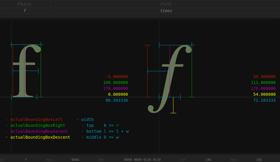
Let's focus on the three horizontal attributes first. The following image from Differences between width and actualBoundingBoxLeft(Right), it can be seen that there is a difference between width and actualBoundingBoxLeft/Right. In short, the latter represents the maximum boundary of the character (the same applies to actualBoundingBoxAscent/Descent in the vertical direction), while the former (blue) is entirely possible to be less than the sum of the latter (red + green), for example, the italic f on the right side of the figure, considering font-kerning, if the next character is still f, these two f can be interleaved side by side.
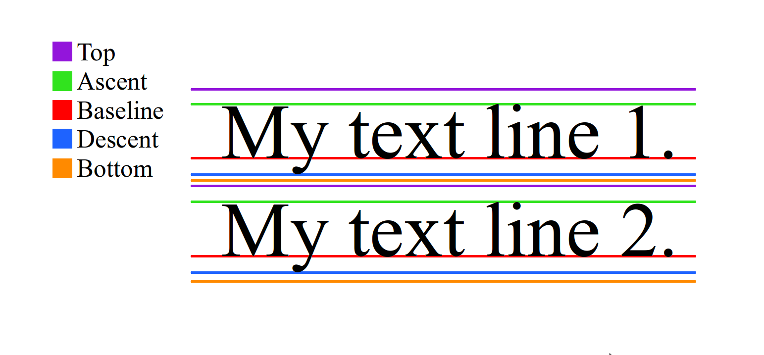
Let's look at the vertical attributes. The following image is from Meaning of top, ascent, baseline, descent, bottom, and leading in Android's FontMetrics. First, find text-baseline, properties ending with Ascent/Descent are based on it:
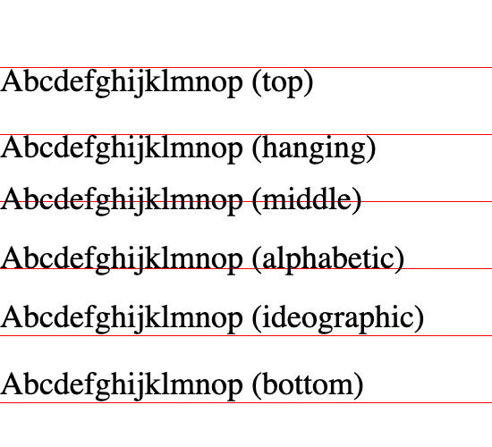
The value of text-baseline can refer to text-baseline, as shown in the figure below. For example, when taking the hanging value, the value of hangingBaseline is 0, and the value of alphabeticBaseline is the distance from alphabetic to hanging.
Finally, fontBoundingBoxAscent/Descent is the maximum boundary of the font itself, and actualBoundingBoxAscent/Descent is the maximum boundary of the font when actually drawn, so the former is suitable for drawing a consistent background for text, which will not appear unevenly high or low with content changes.
measureText
How to obtain TextMetrics? The Canvas 2D API provides measureText, but in actual use, it is necessary to consider the situation where only width is available. Taking PIXI.TextMetrics as an example, it takes this into account in the implementation, if actualBoundingBoxLeft/Right are both 0, then use width:
let textMetrics = PIXI.TextMetrics.measureText('Your text', style);

// @see https://github.com/pixijs/pixijs/blob/dev/src/scene/text/canvas/CanvasTextMetrics.ts#L334
const metrics = context.measureText(text);
let metricWidth = metrics.width;
const actualBoundingBoxLeft = -metrics.actualBoundingBoxLeft;
const actualBoundingBoxRight = metrics.actualBoundingBoxRight;
let boundsWidth = actualBoundingBoxRight - actualBoundingBoxLeft;
return Math.max(metricWidth, boundsWidth);
For font-related attributes, a few representative characters are selected to ensure that Ascent/Descent can be measured, and if it is not obtained, the fontSize value manually entered by the user is used.
// @see https://github.com/pixijs/pixijs/blob/dev/src/scene/text/canvas/CanvasTextMetrics.ts#L779
context.font = font;
const metrics = context.measureText(
    CanvasTextMetrics.METRICS_STRING + // |ÉqÅ
        CanvasTextMetrics.BASELINE_SYMBOL, // M
);

const properties = {
    ascent: metrics.actualBoundingBoxAscent,
    descent: metrics.actualBoundingBoxDescent,
    fontSize:
        metrics.actualBoundingBoxAscent + metrics.actualBoundingBoxDescent,
};

if (fontProperties.fontSize === 0) {
    fontProperties.fontSize = style.fontSize as number;
    fontProperties.ascent = style.fontSize as number;
}
In addition to using the Canvas 2D API, there are also the following options on the browser side:
- opentype.js
- use-gpu uses an ab-glyph based use-gpu-text
- More and more applications are using harfbuzzjs, see: State of Text Rendering 2024
Using HarfBuzz on the web has been on the rise, first transpiled to JavaScript, and more recently cross-compiled to WebAssembly, through harfbuzzjs. Apps like Photopea, an online photo editor, use it that way. Crowbar by Simon Cozens is an OpenType shaping debugger web-app built using the HarfBuzz buffer-messaging API. Sploot is another web-app by Simon, a font inspector. Prezi and Figma also use HarfBuzz in their web-apps.
As stated in What HarfBuzz doesn't do, solving the measurement problem of individual characters is far from enough, next we consider letterSpacing.
HarfBuzz can tell you how wide a shaped piece of text is, which is useful input to a justification algorithm, but it knows nothing about paragraphs, lines or line lengths. Nor will it adjust the space between words to fit them proportionally into a line.
letterSpacing
The Canvas 2D API provides letterSpacing, which can be used to adjust the spacing between characters. We set it before measuring the text:
measureText(
    text: string,
    letterSpacing: number,
    context: ICanvasRenderingContext2D
) {
    context.letterSpacing = `${letterSpacing}px`;
    // Omitted measurement process
}
Subsequently, when arranging the position of each character, it is also necessary to consider, which we will introduce in Generate quads.
Paragraph layout
Individual characters combine to form sentences, and sentences form paragraphs. The following image from Text layout is a loose hierarchy of segmentation shows the hierarchical structure of text layout from the bottom up.
The Canvas 2D API does not provide paragraph-related capabilities in text drawing, only the most basic Drawing text function. CanvasKit, based on Skia, has extended this and additionally provides a drawParagraph method, see: CanvasKit Text Shaping
One of the biggest features that CanvasKit offers over the HTML Canvas API is paragraph shaping.
const paragraph = builder.build();
paragraph.layout(290); // width in pixels to use when wrapping text
canvas.drawParagraph(paragraph, 10, 10);
Let's start with paragraph segmentation.
Paragraph segmentation
The simplest basis for segmentation is explicit line breaks.
const newlines: number[] = [
    0x000a, // line feed
    0x000d, // carriage return
];
In addition, automatic line breaking also needs to be considered. At the same time, let each line be as close to the same length as possible, see: Beautifying map labels with better line breaking
const breakingSpaces: number[] = [
    0x0009, // character tabulation
    0x0020, // space
    0x2000, // en quad
    0x2001, // em quad
    0x2002, // en space
    0x2003, // em space
    0x2004, // three-per-em space
    0x2005, // four-per-em space
    0x2006, // six-per-em space
    0x2008, // punctuation space
    0x2009, // thin space
    0x200a, // hair space
    0x205f, // medium mathematical space
    0x3000, // ideographic space
];
In CJK, some characters cannot appear at the beginning of a line, and some cannot appear at the end. For example, in Chinese, most punctuation marks cannot appear at the beginning of a line. For specific rules, see: Line breaking rules in East Asian languages. pixi-cjk handles these situations:

BiDi
HarfBuzz will not handle BiDi, see What HarfBuzz doesn't do:
HarfBuzz won't help you with bidirectionality.
BiDi
support for handling text containing a mixture of left to right (English) and right to left (Arabic or Hebrew) data.
For example, for this mixed LTR and RTL content ABCאבגDEF, we need to manually change the order of RTL text to display the correct effect:
'ABCאבגDEF'.split(''); // ['A', 'B', 'C', 'ג' ,'ב' ,'א', 'D', 'E', 'F']This issue is not easy to solve in the browser, see: BiDi in Pixi.js. mapbox-gl-rtl-text and rtl-text ported International Components for Unicode (ICU) to WASM which will increase the JS bundle size. However, currently we can use bidi-js to handle it, when encountering RTL characters, we need to manually reverse them:
import bidiFactory from 'bidi-js';

this.#bidi = bidiFactory();
const embeddingLevels = this.#bidi.getEmbeddingLevels(text);
let bidiChars = '';
for (const segment of segmentStack[0]!) {
    const { text, direction } = segment;
    bidiChars += direction === 'ltr' ? text : text.split('').reverse().join('');
}
In printed Arabic, each character can have an “isolated,” “initial,” “medial,” and “final” form. As an example, here are the four forms for the Arabic letter “meem” (U+0645), see: Improving Arabic and Hebrew text in map labels.

We choose JavaScript-Arabic-Reshaper which is much more light-weighted compared with ICU.
import ArabicReshaper from 'arabic-reshaper';

if (direction === 'ltr') {
    bidiChars += text;
} else {
    bidiChars += ArabicReshaper.convertArabic(text)
        .split('')
        .reverse()
        .join('');
}
After solving BiDi, we now need to address the issue of compound characters. The following example comes from cosmic-text, a multi-line text processing library implemented in Rust.
for line in BidiParagraphs::new(&text) {
    for grapheme in line.graphemes(true) {
        for c in grapheme.chars() {}
    }
}
Composite characters
Not all characters are composed of a single character, clusters is the term used by HarfBuzz to handle composite characters
In text shaping, a cluster is a sequence of characters that needs to be treated as a single, indivisible unit.
For example, emoji are, if we process them as a single character (for example, using split('')), whether it is measurement or subsequent drawing will result in incorrect truncation:
'🌹'.length; // 2
'🌹'[0]; // '\uD83C'
'🌹'[1]; //'\uDF39'
On the browser side, we can use a library like grapheme-splitter, the usage is as follows:
var splitter = new GraphemeSplitter();
// plain latin alphabet - nothing spectacular
splitter.splitGraphemes('abcd'); // returns ["a", "b", "c", "d"]
// two-char emojis and six-char combined emoji
splitter.splitGraphemes('🌷🎁💩😜👍🏳️🌈'); // returns ["🌷","🎁","💩","😜","👍","🏳️🌈"]But its size (still 22kB after compression) is not negligible, see BundlePhobia grapheme-splitter. Therefore, in Pixi.js, the browser's own Intl.Segmenter is used by default to handle composite characters, and this feature is supported by most modern browsers:
// @see https://github.com/pixijs/pixijs/blob/dev/src/scene/text/canvas/CanvasTextMetrics.ts#L121C19-L131C10
const splitGraphemes: (s: string) => string[] = (() => {
    if (typeof (Intl as IIntl)?.Segmenter === 'function') {
        const segmenter = new (Intl as IIntl).Segmenter();

        return (s: string) => [...segmenter.segment(s)].map((x) => x.segment);
    }

    return (s: string) => [...s];
})();
We also adopt this solution, which will be used when generating SDF for characters later.
text-align
Implementing text-align is simple:
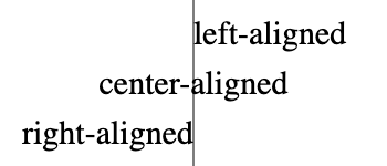
let offsetX = 0;
if (textAlign === 'center') {
    offsetX -= width / 2;
} else if (textAlign === 'right' || textAlign === 'end') {
    offsetX -= width;
}
But implementing vertical alignment is not so simple, text-baseline is only for single-line text, and in many scenarios, we want the entire paragraph to be centered. We will introduce it when we discuss flex layout later.
Rendering
The following image shows the position of the FreeType font rendering engine in the process:

Let's focus on the specific text rendering techniques. For Latin characters with a limited character set, it is entirely possible to generate a glyph atlas offline and upload it to the GPU at runtime, freetype-gl is implemented this way.
The glyph atlas is a single image that will be uploaded as a texture to the GPU along with the rest of the data for the tile. Here’s a visual representation of a glyph atlas:
The following image is from: Drawing Text with Signed Distance Fields in Mapbox GL

But the problem with this non-vector approach is that the characters will be very blurry when enlarged, the following image is from Distance field fonts
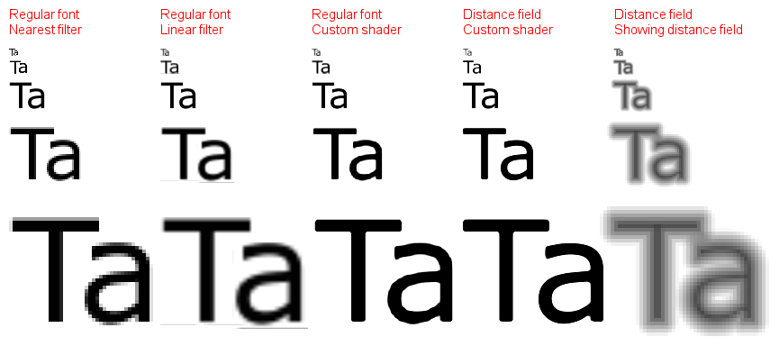
The mainstream SDF-based solution currently comes from Valve's paper Improved Alpha-Tested Magnification for Vector Textures and Special Effects, the advantages of this solution include:
- It remains clear after scaling
- It is easy to implement anti-aliasing, Halo, shadows, and other features
But the problem is that the edges are not sharp enough, although in visualization scenarios, the tolerance is higher, and it can also be optimized through methods such as msdf. In addition, SDF also cannot support font hinting.
Let's first look at the SDF generation situation for a single character.
SDF generation
The following image is from msdf-atlas-gen, we focus on SDF and MSDF these two types of atlases:
| Hard mask | Soft mask | SDF | PSDF | MSDF | MTSDF | |
|---|---|---|---|---|---|---|
| Channels: | 1 (1-bit) | 1 | 1 | 1 | 3 | 4 |
| Anti-aliasing: | - | Yes | Yes | Yes | Yes | Yes |
| Scalability: | - | - | Yes | Yes | Yes | Yes |
| Sharp corners: | - | - | - | - | Yes | Yes |
| Soft effects: | - | - | Yes | - | - | Yes |
| Hard effects: | - | - | - | Yes | Yes | Yes |
If offline generation is allowed, you can use msdf-atlas-gen or node-fontnik (mapbox uses it to generate protocol buffer encoded SDF on the server side). But considering CJK characters, you can use tiny-sdf for runtime generation, the usage is as follows, after passing in the font-related attributes, you get pixel data.
const tinySdf = new TinySDF({
    fontSize: 24,
    fontFamily: 'sans-serif',
});
const glyph = tinySdf.draw('泽'); // Contains pixel data, width and height, character metrics, etc.
Let's briefly analyze its generation principle. First, it uses the browser Canvas2D API getImageData to obtain pixel data, but when writing, there is a buffer margin, which is considered for the implementation of Halo.
const size = (this.size = fontSize + buffer * 4);The most violent traversal method
For a two-dimensional grid, the "distance" in the distance field is the Euclidean distance, so the EDT (Euclidean Distance Transform) is defined as follows. Where
Where the first part is irrelevant to
Therefore, we only need to consider the one-dimensional distance squared:
If we understand the above one-dimensional distance squared field calculation formula from a geometric perspective, it is actually a set of parabolas, each parabola has its lowest point at
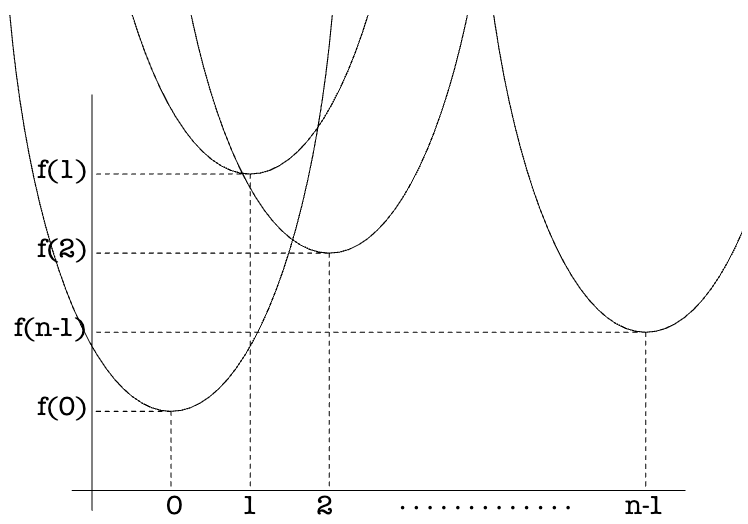
Therefore, the lower bound of this set of parabolas, that is, the solid line part in the following image represents the calculation result of EDT:
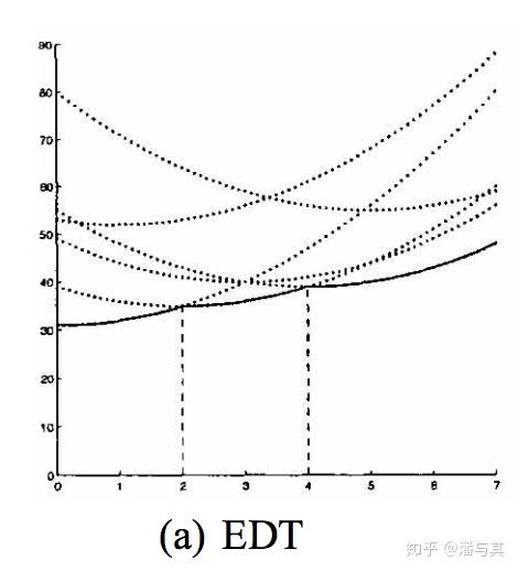
To find this lower bound, we need to calculate the intersection points of any two parabolas, for example, for the two parabolas
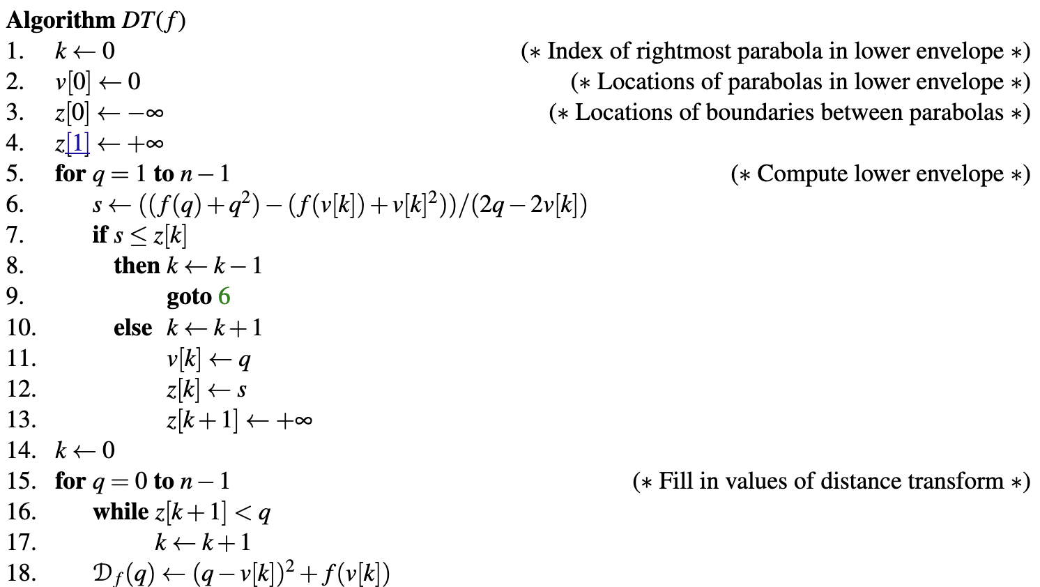
Now that we have the knowledge to calculate EDT 1D, save the sequence number of the rightmost parabola in the lower bound in
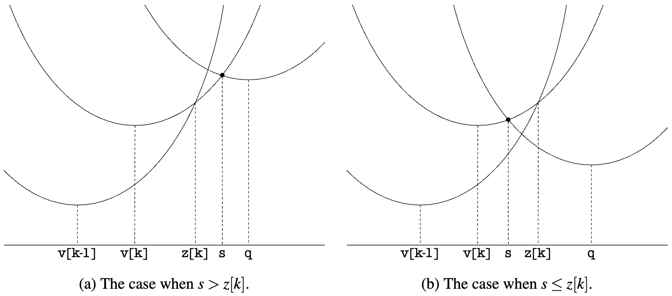
The complete algorithm is as follows, tiny-sdf implements it (EDT 1D), even the variable names are consistent:
Sub-pixel Distance Transform introduces the idea of this algorithm in detail, calculating the outer distance field separately, and then combining the two:
To make a signed distance field, you do this for both the inside and outside separately, and then combine the two as inside – outside or vice versa.
It starts with the most basic 1D, first assuming that our input only has black and white, that is, the Hard mask mentioned above, first calculate the outer distance field:

Next, calculate the inner distance field, I reverses O:
Finally, combine, using the outer distance field minus the inner distance field:
In the implementation of tiny-sdf, the above process corresponds to the processing logic when a is 1:
// @see https://github.com/mapbox/tiny-sdf/blob/main/index.js#L85
gridOuter.fill(INF, 0, len);
gridInner.fill(0, 0, len);

for (let y = 0; y < glyphHeight; y++) {
    for (let x = 0; x < glyphWidth; x++) {
        if (a === 1) {
            // fully drawn pixels
            gridOuter[j] = 0;
            gridInner[j] = INF;
        } else {
        }
    }
}

edt(outer, 0, 0, wp, hp, wp, this.f, this.z, this.v);
edt(inner, pad, pad, w, h, wp, this.f, this.z, this.v);

for (let i = 0; i < np; i++) {
    const d = Math.sqrt(outer[i]) - Math.sqrt(inner[i]);
    out[i] = Math.max(
        0,
        Math.min(255, Math.round(255 - 255 * (d / this.radius + this.cutoff))),
    );
}
For the calculation of 2D EDT, as we introduced at the beginning of this section, it is decomposed into two passes of 1D distance squared, and finally the square root is obtained. Similar to the Gaussian blur effect in post-processing:
Like a Fourier Transform, you can apply it to 2D images by applying it horizontally on each row X, then vertically on each column Y (or vice versa).
Here you can also directly see that for a grid of height * width size, the complexity is
// @see https://github.com/mapbox/tiny-sdf/blob/main/index.js#L110
function edt(data, width, height, f, d, v, z) {
    // Pass 1
    for (var x = 0; x < width; x++) {
        for (var y = 0; y < height; y++) {
            f[y] = data[y * width + x];
        }
        // Fix x and calculate 1D distance squared
        edt1d(f, d, v, z, height);
        for (y = 0; y < height; y++) {
            data[y * width + x] = d[y];
        }
    }
    // Pass 2
    for (y = 0; y < height; y++) {
        for (x = 0; x < width; x++) {
            f[x] = data[y * width + x];
        }
        edt1d(f, d, v, z, width);
        for (x = 0; x < width; x++) {
            // Take the square root to get the Euclidean distance
            data[y * width + x] = Math.sqrt(d[x]);
        }
    }
}
Solving the problem of SDF generation for a single character, the next step is to merge all character SDFs into a large image, which will be used as a texture later.
Glyph atlas
The single SDF needs to be merged into a large image to be used as a texture later, similar to CSS Sprite. This kind of problem is called: Bin packing problem, putting a small box into a large box, using space reasonably to reduce gaps. We choose potpack, this algorithm can get a result close to a square as much as possible, the disadvantage is that after generating the layout, it is not allowed to modify, only re-generate.

It should be noted that this atlas contains all the fonts used in the scene, so when fontFamily/Weight changes, old text changes, and new text is added, it needs to be re-generated, but the font size change should not re-generate. Therefore, to avoid frequent re-generation, for each font, the default is to generate SDF for commonly used characters from 32 to 128.
This texture only needs to use one channel, if it is in WebGL, you can use gl.ALPHA format, but there is no corresponding format in WebGPU. Therefore, we use Format.U8_R_NORM format, which is gl.LUMINANCE in WebGL and r8unorm in WebGPU.
this.glyphAtlasTexture = device.createTexture({
    ...makeTextureDescriptor2D(Format.U8_R_NORM, atlasWidth, atlasHeight, 1),
    pixelStore: {
        unpackFlipY: false,
        unpackAlignment: 1,
    },
});
Then in the Shader, the signed distance is obtained from the r channel:
uniform sampler2D u_SDFMap; // glyph atlas
varying vec2 v_UV;

float dist = texture2D(u_SDFMap, v_UV).r;
The above is the drawing logic in the fragment shader, let's take a look at how to calculate the position of each character passed into the vertex shader.
Generate quads
First, we need to convert each glyph from glyph data to two triangles (called "quad"), containing four vertices:

The simplified glyph data SymbolQuad is defined as follows:
// @see https://github.com/mapbox/mapbox-gl-js/blob/main/src/symbol/quads.ts#L42
export type SymbolQuad = {
    tl: Point; // The coordinates of the four vertices in local coordinates
    tr: Point;
    bl: Point;
    br: Point;
    tex: {
        x: number; // Texture coordinates
        y: number;
        w: number;
        h: number;
    };
};
For each glyph data, split it into four vertices, where uv and offset are combined into one stride, and then accessed in the vertex shader through a_UvOffset:
glyphQuads.forEach((quad) => {
    charUVOffsetBuffer.push(quad.tex.x, quad.tex.y, quad.tl.x, quad.tl.y);
    charUVOffsetBuffer.push(
        quad.tex.x + quad.tex.w,
        quad.tex.y,
        quad.tr.x,
        quad.tr.y,
    );
    charUVOffsetBuffer.push(
        quad.tex.x + quad.tex.w,
        quad.tex.y + quad.tex.h,
        quad.br.x,
        quad.br.y,
    );
    charUVOffsetBuffer.push(
        quad.tex.x,
        quad.tex.y + quad.tex.h,
        quad.bl.x,
        quad.bl.y,
    );
    charPositionsBuffer.push(x, y, x, y, x, y, x, y);

    indexBuffer.push(0 + i, 2 + i, 1 + i);
    indexBuffer.push(2 + i, 0 + i, 3 + i);
    i += 4;
});
In the vertex shader, divide uv by the texture size to get the texture coordinates passed into the fragment shader to sample the glyph atlas. At the same time, multiply the offset by the font scale to get the offset relative to the anchor point, and finally add the position and offset to get the final vertex position:
v_Uv = a_UvOffset.xy / u_AtlasSize;

vec2 offset = a_UvOffset.zw * fontScale;
gl_Position = vec4((u_ProjectionMatrix
    * u_ViewMatrix
    * u_ModelMatrix
    * vec3(a_Position + offset, 1)).xy, zIndex, 1);
Finally, let's see how to calculate the glyph data. After paragraph segmentation in the previous section, we got an array of strings for multiple lines lines, combined with textAlign letterSpacing and fontMetrics to calculate the position information of each character relative to the anchor point.
function layout(
    lines: string[], // after paragraph segmentation
    fontStack: string,
    lineHeight: number,
    textAlign: CanvasTextAlign,
    letterSpacing: number,
    fontMetrics: globalThis.TextMetrics & { fontSize: number },
): PositionedGlyph[] {}
Here we refer to the implementation of mapbox-gl-js shaping.ts:
export type PositionedGlyph = {
    glyph: number; // charCode
    x: number;
    y: number;
    scale: number; // The scale ratio calculated according to the zoom level
    fontStack: string;
};lines.forEach((line) => {
const lineStartIndex = positionedGlyphs.length;
canvasTextMetrics.splitGraphemes(line).forEach((char) => {});
});Improvements
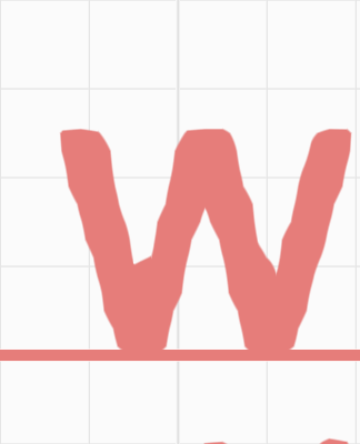
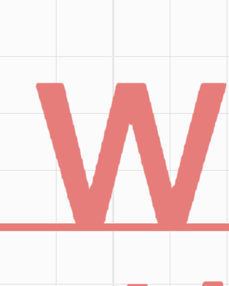
The text rendered currently has obvious "artificial traces" when enlarged, one obvious reason is the resolution of the generated SDF. In the current implementation of Mapbox, SDF_SCALE is used to control it, the higher the resolution of the generated SDF, the more delicate it is, but it also brings a decline in performance.
https://github.com/mapbox/mapbox-gl-js/blob/main/src/render/glyph_manager.ts#L34
The choice of SDF_SCALE is a trade-off between performance and quality. Glyph generation time grows quadratically with the the scale, while quality improvements drop off rapidly when the scale is higher than the pixel ratio of the device. The scale of 2 buys noticeable improvements on HDPI screens at acceptable cost.
The following image shows the comparison effect when zoomed in with SDF_SCALE values of 1 and 4:
| SDF_SCALE = 1 | SDF_SCALE = 4 |
|---|---|
 |  |
But first, let's not adjust the SDF resolution. The current implementation of tiny-sdf still has problems.
Sub-pixel Distance Transform
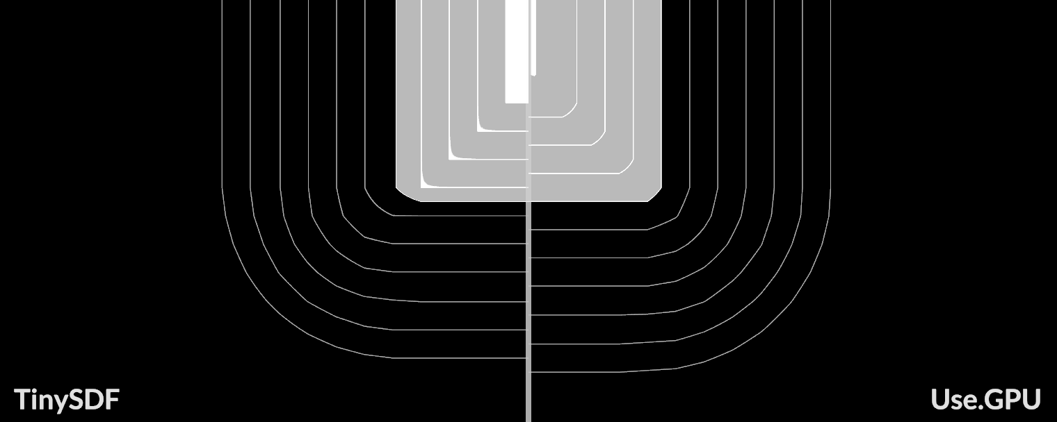
Sub-pixel Distance Transform points out that there are problems with the implementation of tiny-sdf, and provides an improved implementation.
First, we use Canvas to generate not just black and white Hard mask, but a grayscale image:

In the implementation of tiny-sdf, when a is not 1, it is processed as follows:
// @see https://github.com/mapbox/tiny-sdf/blob/main/index.js#L89
if (a === 1) {
} else {
    const d = 0.5 - a; // aliased pixels
    gridOuter[j] = d > 0 ? d * d : 0;
    gridInner[j] = d < 0 ? d * d : 0;
}
MSDF
When using a low-resolution distance field for reconstruction, the corners of the characters are too smooth and cannot maintain their original sharpness. Now let's solve this problem.

The distance field can be subjected to set operations. The following image is from Shape Decomposition for Multi-channel Distance Fields, we store the two distance fields in two components of the bitmap (R, G), respectively. When reconstructing, although these two distance fields are smooth at the corners, the intersection can be used to get a sharp restoration effect:

The decomposition algorithm can refer to the original paper Shape Decomposition for Multi-channel Distance Fields in section 4.4: Direct multi-channel distance field construction. In actual use, the author provides msdfgen, it can be seen that MSDF has a much better effect at low resolution, even better than higher resolution SDF.
In terms of generating tools, online tools include MSDF font generator, and CLI tools include msdf-bmfont-xml. These tools generate an MSDF atlas at the same time, and also generate an fnt or json file, which contains the layout information of each character for subsequent drawing. pixi-msdf-text is a complete example using Pixi.js, which uses BitmapFontLoader to load the fnt file, and our project also references its implementation.
When reconstructing with median in the Fragment Shader:
float median(float r, float g, float b) {
  return max(min(r, g), min(max(r, g), b));
}

#ifdef USE_MSDF
    vec3 s = texture(SAMPLER_2D(u_Texture), v_Uv).rgb;
    float dist = median(s.r, s.g, s.b);
#else
In the example below, you can see that the characters remain sharp even when zoomed in:
font-kerning
In pre-generated Bitmap fonts, kernings can be included, which can adjust the spacing between two characters in a fixed sequence.
For example https://pixijs.com/assets/bitmap-font/desyrel.xml
<kernings count="1816">
    <kerning first="102" second="102" amount="2" />
    <kerning first="102" second="106" amount="-2" />
</kernings>
Both bounding box calculation and layout need to take it into account. The following example shows the differences:
In runtime, if we want to get font-kerning, we can refer to the way given by https://github.com/mapbox/tiny-sdf/issues/6#issuecomment-1532395796:
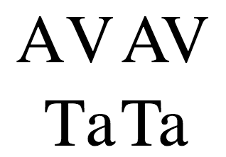
const unkernedWidth =
    tinySdf.ctx.measureText('A').width + tinySdf.ctx.measureText('V').width;
const kernedWidth = tinySdf.ctx.measureText('AV').width;
const kerning = kernedWidth - unkernedWidth; // a negative value indicates you should adjust the SDFs closer together by that much
emoji
In some emoji rendering implementations, such as EmojiEngine, a pre-generated emoji atlas approach is used. However, this approach not only has texture size limitations but also cannot maintain the platform-specific emoji appearance across different platforms. Therefore, similar to SDF, we want to generate emojis on-demand at runtime on the current platform.
The biggest difference between this approach and SDF is that we cannot only preserve the alpha channel, but need to retain all three RGB channels for subsequent distance field reconstruction.
Extended reading
- State of Text Rendering 2024
- Signed Distance Field Fonts - basics
- Approaches to robust realtime text rendering in threejs (and WebGL in general)
- Easy Scalable Text Rendering on the GPU
- Text Visualization Browser
- Rive Text Overview
- Texture-less Text Rendering
- Text layout is a loose hierarchy of segmentation
- End-To-End Tour of Text Layout/Rendering
- Text rendering in mapbox
- Rendering Crispy Text On The GPU
- Localization, languages, and listening
- RTL languages in Figma