Lesson 30 - Post-processing and render graph
In this lesson, we revisit traditional shader-based post-processing for images (fullscreen passes, sampling, and common effects), then introduce how to use a render graph to organize multiple passes, manage render targets and synchronization, and optimize the full post-processing pipeline.
Post-processing Effects
Based on Shaders, common image processing effects can be achieved, such as Gaussian blur, Perlin noise, Glitch, and of course, the recently popular "liquid glass":
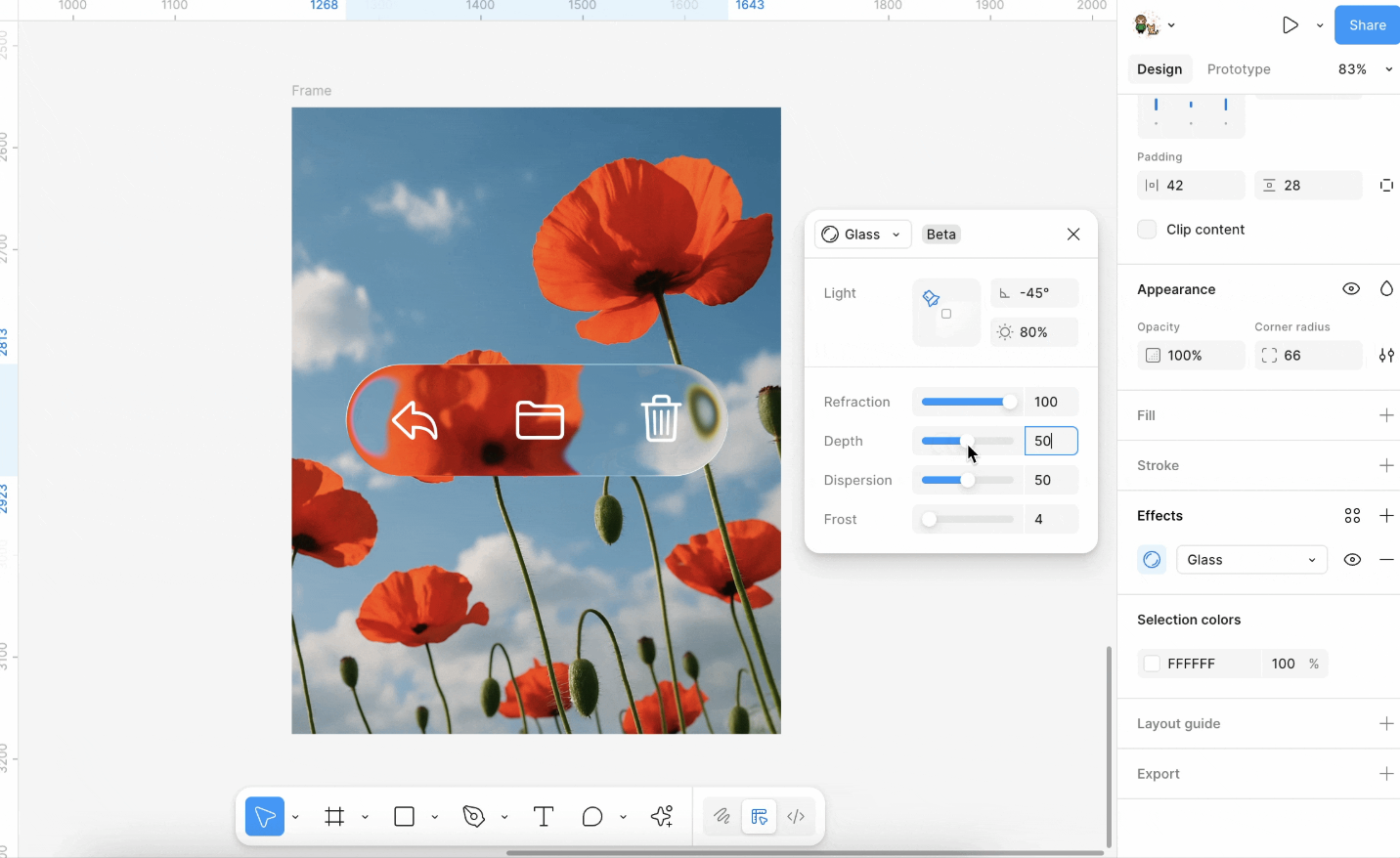
For more effects, see:
In implementation, Pixi.js filters calculate the application area based on the object's bounding box, render the object onto a temporary render texture, and then apply shader effects to that texture.
Render to RenderTarget
In Pixi.js:
// src/filters/FilterSystem.ts
const quadGeometry = new Geometry({
    attributes: {
        aPosition: {
            buffer: new Float32Array([0, 0, 1, 0, 1, 1, 0, 1]),
            format: 'float32x2',
            stride: 2 * 4,
            offset: 0,
        },
    },
    indexBuffer: new Uint32Array([0, 1, 2, 0, 2, 3]),
});
Sample
Next, we need to sample the area where the target shape is located from the texture of the entire canvas:
void main() {
v_Uv = a_Position * (u_OutputFrame.zw / u_InputSize.xy) + u_OutputFrame.xy / u_InputSize.xy;
gl_Position = vec4((a_Position * 2.0 - 1.0) * u_OutputTexture.xy / u_OutputFrame.zw * u_OutputTexture.z, 0.0, 1.0);
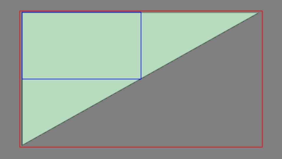
}Big triangle
Here we can use a full-screen triangle, which reduces one vertex compared to a Quad, see: Optimizing Triangles for a Full-screen Pass
this.#bigTriangleVertexBuffer = this.device.createBuffer({
    viewOrSize: new Float32Array([1, 3, -3, -1, 1, -1]),
    usage: BufferUsage.VERTEX,
    hint: BufferFrequencyHint.DYNAMIC,
});
The vertex shader is very simple; it only needs to correctly map the v_Uv texture coordinates:
void main() {
v_Uv = 0.5 * (a_Position + 1.0);
gl_Position = vec4(a_Position, 0.0, 1.0);
#ifdef VIEWPORT_ORIGIN_TL
v_Uv.y = 1.0 - v_Uv.y;
#endif
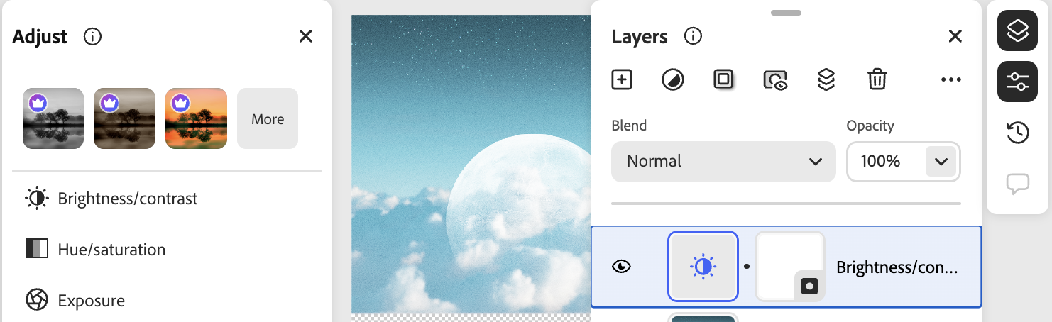
}Brightness and contrast
We can use the CSS filter syntax, for example filter: brightness(0.4);
In implementation, a single shader suffices; see brightnesscontrast.js.
uniform sampler2D u_Texture;
in vec2 v_Uv;

layout(std140) uniform PostProcessingUniforms {
  vec4 u_BrightnessContrast;
};

out vec4 outputColor;

void main() {
  vec4 color = texture(SAMPLER_2D(u_Texture), v_Uv);
  float brightness = u_BrightnessContrast.x;
  float contrast = u_BrightnessContrast.y;

  if (color.a > 0.0) {
    color.rgb /= color.a;
    color.rgb += brightness;
    if (contrast > 0.0) {
      color.rgb = (color.rgb - 0.5) / (1.0 - contrast) + 0.5;
    } else {
      color.rgb = (color.rgb - 0.5) * (1.0 + contrast) + 0.5;
    }
    color.rgb *= color.a;
  }

  outputColor = color;
}
Noise
Noise in post-processing is usually generated from screen UV as pseudo-random values overlaid on RGB, simulating film grain, signal interference, and similar effects. The implementation in this tutorial follows glfx.js’s noise filter, using uniform randomness and a strength factor u_Noise to control the perturbation. Before writing, colors are unpremultiplied and multiplied back by alpha to avoid gray edges on transparency.
In the filter string you can write noise(0.1); the value in parentheses is strength (roughly 0–1). If you start from design tools, you can also compare Spline’s Noise Layer: it similarly stacks procedural noise on materials/fills; here we apply a full-screen pass on an already rasterized texture.
Halftone
Halftone modulates lightness with a regular pattern to simulate print dots.
- Dot (halftone screen): See Pixi
dot.frag: samplesin(x)·sin(y)in rotated coordinates for black-and-white dots; can pair with grayscale for old print and comic halftone.filterexample:dot(1, 5, 1)(scale, angle, grayscale on/off). - Color halftone: See glfx
colorhalftone.js: treat RGB in a CMY/K style and modulate cyan, magenta, yellow, and black with four sine grids at different phases for a color-print look. Shorthandcolor-halftone(6)(dot diameter only), orcolor-halftone(6, 0.5)(diameter and angle in radians); the full four-parameter form can set pattern center and angle.
float halftonePattern(float rotAngle) {
// Continuous sine screen; no dot shape, grain, hex grid, etc.
  float s = sin(rotAngle), c = cos(rotAngle);
  vec2 tex = v_Uv * u_CH1.xy - u_CH0.xy;
  vec2 point = vec2(
    c * tex.x - s * tex.y,
    s * tex.x + c * tex.y
  ) * u_CH0.w;
  return (sin(point.x) * sin(point.y)) * 4.0;
}

void main() {
  vec4 color = texture(SAMPLER_2D(u_Texture), v_Uv);
  // ...
  vec3 cmy = 1.0 - color.rgb; // CMYK separation
  float k = min(cmy.x, min(cmy.y, cmy.z));
  // ...
  cmy = clamp(
    cmy * 10.0 - 3.0 + vec3(
      halftonePattern(baseAngle + 0.26179),
      halftonePattern(baseAngle + 1.30899),
      halftonePattern(baseAngle)
    ),
    0.0,
    1.0
  );
  k = clamp(k * 10.0 - 5.0 + halftonePattern(baseAngle + 0.78539), 0.0, 1.0);
  vec3 rgb = 1.0 - cmy - vec3(k);
  // ...
}
Paper Shaders takes another approach, supporting large newspaper-style dots, dot size tied to lightness, and swappable dot shapes, hex grids, grain, and more.
Pixelate
Sample and enlarge blocks for a mosaic; see Pixi pixelate.frag, e.g. pixelate(12px). You can also apply it to gradients with noise overlaid.
CRT & vignette
Mimic an old CRT look, plus vignette:
Glitch
Ascii
First divide the image into cells using uSize and compute grayscale; pick a bitmap constant n from the gray level, then for each pixel in the cell use bits of n to decide light/dark and multiply into the color. This is the usual bitmap-font / ASCII-art approach—not vector glyphs or textured fonts.
float n = 65536.0;
if (gray > 0.2) n = 65600.0; // .
if (gray > 0.3) n = 332772.0; // :
if (gray > 0.4) n = 15255086.0; // *
if (gray > 0.5) n = 23385164.0; // o
Liquid glass
Liquid metal
Heatmap
Gen smoke
Time animation
Some post-processing effects can be animated; typically a per-frame time value is passed in (similar to u_Time on Shadertoy):
export class PostEffectTime extends System {
    execute() {
        setPostEffectEngineTimeSeconds(perf.now() / 1000);
    }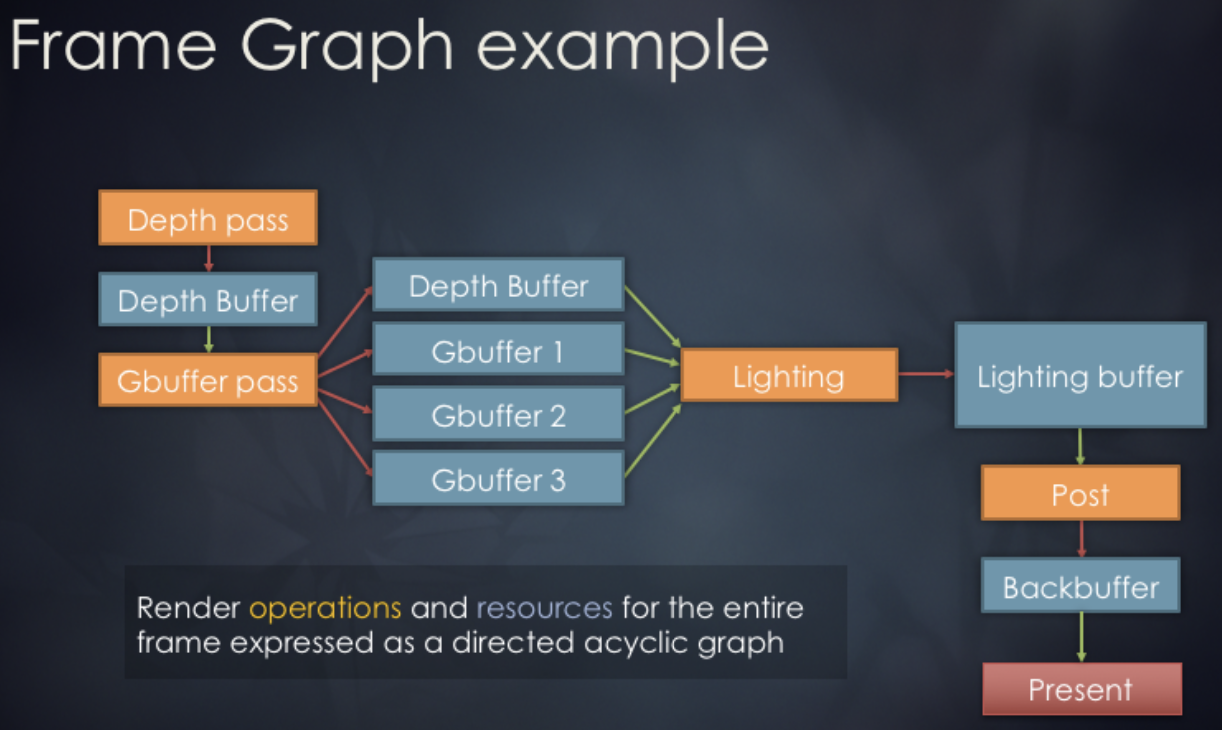
}Render graph
A Render Graph (sometimes called a FrameGraph) is a modern rendering architecture that models the rendering process as a directed acyclic graph (DAG). In this model, each rendering pass and the resources it uses are treated as nodes and edges; the graph structure automatically manages resource state transitions, synchronization, and lifetimes.
Usage in Render graph in bevy is as follows:
// @see https://docs.rs/bevy/latest/bevy/render/render_graph/struct.RenderGraph.html
let mut graph = RenderGraph::default();
graph.add_node(Labels::A, MyNode);
graph.add_node(Labels::B, MyNode);
graph.add_node_edge(Labels::B, Labels::A);
Design concept
We reference the render graph implementation from noclip, which employs a three-phase design:
Graph Building Phase: Declaratively defines the rendering pipeline. We'll see how it's used in the next subsection.
Scheduling Phase: Automatically allocates and reuses resources. This can be further broken down into:
- Statistics Phase: Traverse all passes to count references for each RenderTarget and ResolveTexture
- Allocation Phase: Allocate resources on demand. Retrieve from the object pool or create on first use. Reuse resources with identical specifications. Return to the object pool when reference count reaches zero.
- Release Phase: Return to the object pool when reference count reaches zero.
Execution Phase: Execute rendering passes sequentially.
The data structure for the render graph is as follows. It stores a declarative description of the render graph, containing no actual resources. It only records the ID relationships between Passes and Render Targets.
class GraphImpl {
    renderTargetDescriptions: Readonly<RGRenderTargetDescription>[] = [];
    resolveTextureRenderTargetIDs: number[] = [];
    passes: RenderGraphPass[] = [];
}
Usage
Each time a repaint is required, a new RenderGraphBuilder is created to construct the DAG. Currently, this simple DAG includes a main rendering pass that outputs results to a ColorRT and DepthRT. Subsequently, we will add additional passes using pushPass. The ColorRT can be consumed as input, and ultimately this ColorRT will be rendered to the screen. The main rendering logic is written in the callback function of pass.exec, which receives a RenderPass object. For details, see: Lesson 2.
const builder = renderGraph.newGraphBuilder();
builder.pushPass((pass) => {
    pass.setDebugName('Main Render Pass');
    pass.attachRenderTargetID(RGAttachmentSlot.Color0, mainColorTargetID);
    pass.attachRenderTargetID(RGAttachmentSlot.DepthStencil, mainDepthTargetID);
    pass.exec((renderPass) => {
        // Render grid
        // Render shapes in current scene
    });
});
builder.resolveRenderTargetToExternalTexture(
    mainColorTargetID,
    onscreenTexture,
);
renderGraph.execute();
FXAA
We now create a separate FXAA pass outside the main render pass for fast anti-aliasing. Unlike traditional methods such as MSAA based on geometric sampling, FXAA does not require extra samples or knowledge of scene geometry; it processes the final pixels directly, so the performance cost is very low. This method converts RGB to grayscale using NTSC weights 0.299R + 0.587G + 0.114B for edge detection:
float MonochromeNTSC(vec3 t_Color) {
  // NTSC primaries.
  return dot(t_Color.rgb, vec3(0.299, 0.587, 0.114));
}
Returning to the declarative syntax of the render graph. First, obtain the ColorRT from the previous step:
builder.pushPass((pass) => {
    pass.setDebugName('FXAA');
    pass.attachRenderTargetID(RGAttachmentSlot.Color0, mainColorTargetID);

    const mainColorResolveTextureID =
        builder.resolveRenderTarget(mainColorTargetID);
    pass.attachResolveTexture(mainColorResolveTextureID);

    pass.exec((passRenderer, scope) => {
        postProcessingRenderer.render(
            passRenderer,
            scope.getResolveTextureForID(mainColorResolveTextureID),
        );
    });
});
We apply the following three post-processing effects to the whole canvas:
api.setAppState({
    filter: 'fxaa() brightness(0.8) noise(0.1)',
});